EasyManua.ls Logo

Febco 850-200 - User Manual

Febco 850-200
2 pages
Print Icon
To Next Page IconTo Next Page
Loading...
IS-F -850DC
INSTALLATION INSTRUCTIONS
Installation Instructions
1. Consult local codes for specific installation requirements and restrictions
applicable to your area.
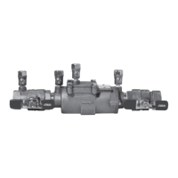
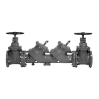
2. These instructions apply to Series 850 (DC) and 850U (DC) sizes
1
/2" to 2"
(15-50mm) only. The valves may be installed only in the orientation/flow
direction shown.
3. The valve assembly must be installed where it is accessible for periodic
testing and maintenance. The recommended clearances shown in the
installation views apply to the exterior, interior and pit/vault installations.
These minimums do not apply to removable protective enclosures.
4. PRIOR TO INSTALLING THE VALVE INTO THE LINE, FLUSH THE
SUPPLY LINE OF ALL FOREIGN MATERIAL. Failure to flush the sup-
ply line may cause the check valves to become fouled and require disas-
sembly and cleaning.
5. After installation, SLOWLY fill the assembly with water and bleed air
from the body using the # 3 and #4 test cocks. Test the valve assembly
to ensure correct operation.
NOTE: All assemblies are tested at the factory for proper operation
and leakage. If the valve does not pass the field test, it is most likely
due to a fouled check valve. This is not covered by the factory warranty.
The valve cover must be removed and the check seats inspected and
cleaned. Any damage or improper operation caused by pipeline debris
or improper installation/start-up is not included in the factory warranty.
In case of a possible warranty claim, contact your local supplier or
FEBCO Representative. DO NOT REMOVE THE VALVE ASSEMBLY
FROM THE PIPELINE.
6. The assembly must be protected from freezing and excessive pressure
increases. Pressure increases can be caused by thermal expansion or
water hammer. These excessive pressure situations must be eliminated
to protect the valve and system from possible damage.
7. Plastic test cock plugs and tethers are provided (loose in box)
for the
1
/2" to 2" (15-50mm) product for those who want to use them.
Service and Maintenance
1. Rinse all parts with water prior to re-assembly.
2. DO NOT USE ANY PIPE DOPE, OIL, GREASE OR SOLVENT ON
ANY PART UNLESS INSTRUCTED TO DO SO.
3. Do not force parts. Parts should fit together freely. Excess force may
cause damage and render the assembly inoperable.
4. Carefully inspect the seals and seating surfaces for debris or damage.
5. Test the assembly after servicing to ensure proper operation.
Check Valves Disassembly
1. Close inlet and outlet ball valves. Bleed residual pressure by opening
No. 2, 3, and 4 test cocks. Allow the test cocks to remain open until
the re-assembly is complete. Test cock No. 1 should remain closed.
2. Remove cover bolts using the appropriate size wrench.
3. Remove spacer by grasping the flanged end of the spacer and pulling
straight up.
4. Remove the inlet check assembly by pulling it in the direction of flow
out from the body bore until it is completely exposed then lift out of the
body.
5. Remove the outlet check assembly by placing the tip of a medium size,
flat nose screwdriver in the slot of the seat and prying the check assem-
bly back until the red O-ring is exposed. Then using your fingers, pull it
out of the body bore until it is completely exposed then lift it out of the
body.
Series 850
Double Check Valve Assemblies
Sizes:
1
2" - 2" (15 50mm)
850
Question and Answer IconNeed help?

Do you have a question about the Febco 850-200 and is the answer not in the manual?

Overview

The device described in the manual is a FEBCO Series 850 Double Check Valve Assembly, available in sizes from 1/2" to 2" (15 – 50mm). This assembly is designed to prevent backflow in water supply lines, specifically to protect potable water from contamination due to backpressure or backsiphonage from non-potable sources. It achieves this by incorporating two independently operating check valves in series, ensuring that if one check valve fails, the other can still provide protection.

Function Description:

The primary function of the Series 850 Double Check Valve Assembly is to provide backflow prevention in water distribution systems. It is a mechanical device that allows water to flow in only one direction. Should there be a reversal of flow (backflow) due to either backpressure (pressure downstream of the assembly exceeding the supply pressure) or backsiphonage (a vacuum or negative pressure in the supply line), the check valves are designed to close, preventing the contaminated water from flowing back into the potable water supply. The "double check" design provides a redundant layer of protection, meaning that if the first check valve fails to seal completely, the second check valve acts as a backup to maintain the integrity of the potable water supply.

Important Technical Specifications:

  • Sizes: 1/2" to 2" (15 – 50mm). This range indicates that the device is suitable for residential, light commercial, and some industrial applications where these pipe sizes are common.
  • Type: Double Check Valve Assembly (DC). The manual also mentions 850U (DC), suggesting a variation, possibly a union end model, within the same series.
  • Orientation: The valves may only be installed in the orientation/flow direction shown in the diagrams. The manual illustrates both horizontal and vertical (flow up or down) installation options, with specific minimum clearance requirements.
  • Materials: While not explicitly detailed in the provided text, typical double check valve assemblies are constructed from durable materials like bronze or stainless steel for the body, with rubber or elastomeric components for the check discs and O-rings, designed to withstand water pressure and resist corrosion. The mention of "plastic test cock plugs and tethers" indicates some plastic components are used for accessories.

Usage Features:

  • Installation Flexibility: The manual provides instructions for both horizontal and vertical flow installations, offering versatility in plumbing configurations.
  • Accessibility for Maintenance: Emphasizes the importance of installing the assembly where it is accessible for periodic testing and maintenance. Specific minimum clearances (e.g., 12" min to fixed structure for horizontal, 3" min for vertical, 18" min for horizontal top view) are provided to ensure adequate space for servicing.
  • Pre-installation Flushing: Crucial instruction to flush the supply line of all foreign material prior to installation. This prevents fouling of the check valves, which could lead to malfunction and necessitate early disassembly and cleaning.
  • Post-installation Testing: After installation, the assembly must be slowly filled with water, air bled using test cocks #3 and #4, and then tested to ensure correct operation. This confirms the device is functioning as intended immediately after setup.
  • Protection from Environmental Factors: Requires protection from freezing and excessive pressure increases (e.g., thermal expansion, water hammer), which can damage the valve and the system.
  • Test Cocks: The presence of test cocks (#1, #2, #3, #4) is a key feature for field testing the assembly to verify its proper operation and compliance with backflow prevention standards.

Maintenance Features:

  • Factory Testing: All assemblies are factory-tested for proper operation and leakage, providing assurance of initial quality.
  • Troubleshooting Guidance: If the valve fails a field test, the manual suggests a "fouled check valve" as the most likely cause, guiding technicians towards inspection and cleaning of the check seats.
  • Disassembly Instructions: Detailed steps are provided for disassembling the check valves:
    • Closing inlet and outlet ball valves.
    • Bleeding residual pressure via test cocks #2, #3, and #4 (test cock #1 remains closed).
    • Removing cover bolts.
    • Removing the spacer.
    • Removing the inlet check assembly by pulling it in the direction of flow.
    • Removing the outlet check assembly by prying it back with a flat nose screwdriver to expose the O-ring, then pulling it out.
  • Reassembly Guidelines:
    • Rinsing all parts with water prior to re-assembly.
    • Strict warning against using pipe dope, oil, grease, or solvent unless specifically instructed, to prevent damage to components.
    • Emphasis on not forcing parts, as they should fit together freely, to avoid damage and ensure proper function.
    • Instruction to carefully inspect seals and seating surfaces for debris or damage during maintenance.
    • Requirement to test the assembly after servicing to ensure proper operation.
  • Warranty Information: The manual includes a limited warranty for defects in material and workmanship for one year from the date of original shipment, with specific disclaimers regarding incidental or consequential damages and improper installation/maintenance. It also notes that factory warranty does not cover issues caused by fouled check valves or improper installation/start-up.
  • California Proposition 65 Warning: Includes a warning about chemicals known to the State of California to cause cancer and birth defects or other reproductive harm, indicating the presence of certain materials in the product that require this disclosure.

Febco 850-200 Specifications

General IconGeneral
BrandFebco
Model850-200
CategoryControl Unit
LanguageEnglish

Related product manuals