EasyManua.ls Logo

Federal Signal VAMA AS-422 User Manual

Federal Signal VAMA AS-422
50 pages
Go to English
To Next Page IconTo Next Page
Page #1 background imageLoading...
Page #1 background image
FEDERAL SIGNAL
V
A
M
A
SIRENA ELECTRONICA
ELECTRONIC SIREN
ELEKTRONISCHE SIRENE
AS- 422
MANUAL DE INSTALACIÓN E INSTRUCCIONES DE
FUNCIONAMIENTO
INSTALLATION AND OPERATING INSTRUCTIONS
MONTAGE-UND BEDIENUNGSANLEITUNG
C:\ ARCHIVO\ DOCUMENT\ SIRENA
REF. DOC.9147659
F.U.R.: 14/4/98 REVISIÓN 1
FEDERAL SIGNAL VAMA-C/Dr.Ferrán,7 (08339)VILASSAR DE DALT SPAIN-Tel:34 3 741 79 00 -Telefax:343 753.03.62
Question and Answer IconNeed help?

Do you have a question about the Federal Signal VAMA AS-422 and is the answer not in the manual?

Federal Signal VAMA AS-422 Specifications

General IconGeneral
BrandFederal Signal VAMA
ModelAS-422
CategoryCar Alarm
LanguageEnglish

Summary

General Description

Configuration for Failure Detection in Main Warning Lights

Details how to configure the amplifier for main warning light failure detection.

Important Notes on Installation and Handling

Covers waterproofing, polarity, and potential fuse issues.

Specifications

Amplifier and Light Specifications

Lists operating current, frequency, voltage, power, light controls, and lamp failure detection.

Safety Instructions for the Installer

Pre-installation Checks and Precautions

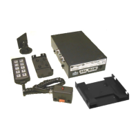
Emphasizes reading manual, electrical knowledge, battery connection, and drilling safety.

Required Tools and Materials

Lists necessary tools like drills, bits, and screwdrivers for installation.

Package Contents

Included Wiring and Screws

Lists types and quantities of wires, connectors, and screws included.

Installation of Control Head and Connection Box

Installation of the Amplifier

Wiring Diagram 1: Standard Configuration

Wiring Diagram 2: Lamp Failure Detection (Two Rotators)

Wiring Diagram 3: Lamp Failure Detection (One Rotator)

Wiring Diagram 4: Lamp Failure Detection (Two Strobe Lights)

Appendix 1: Configuration for Failure Detection in Main Warning Lights

Rotating Lights Configuration

Explains bridge settings for two or one rotating lights for lamp failure detection.

Strobe Lights Configuration

Explains bridge settings for strobe lights for lamp failure detection.

Components Layout

Internal Component Identification

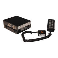
Identifies internal components like fuses, bridges (JP1, JP2, JP3), and volume potentiometer.

Operating Instructions

Siren Control Functions

Explains OFF, MANUAL, WAIL, and YELP siren modes and their operation.

Public Address and Radio Functions

Covers public address operation, volume adjustment, and radiotelephone input.

Light Control Functions

Details activation of Main Warning Lights and Auxiliary Lights.

Horn Control for Siren Operation

Explains how to control the siren using the vehicle's horn or a manual button.

Checking After Installation

System Operation Verification

Steps to test siren sounds, horn control, and radiotelephone volume.

Related product manuals