IA // ROUTING MANUAL
22
IA with Mechanical Drivetrains
PARTS
(2) Brake hoses
(4) 4mm shift housing sections (see Appendix A, “Wire & Hose Lengths”)
(1) Felt 8mm port, 4mm hole, conical grommet
(1) Felt 8mm grommet plug
NOTE
In the following diagrams, blue, purple, and green components are electronic wires; and red compo-
nents are brake hoses.
SHIFTERS & DERAILLEURS
NOTE
In the following diagrams, blue components are shifter cables, and red components are brake hoses.
STEP 1
Start by cutting two (2) pieces of housing for the left and right extensions. Then refer to Appendix A
“Wire & Hose Lengths” and cut the two (2) additional lengths of housing as needed for your frame size.
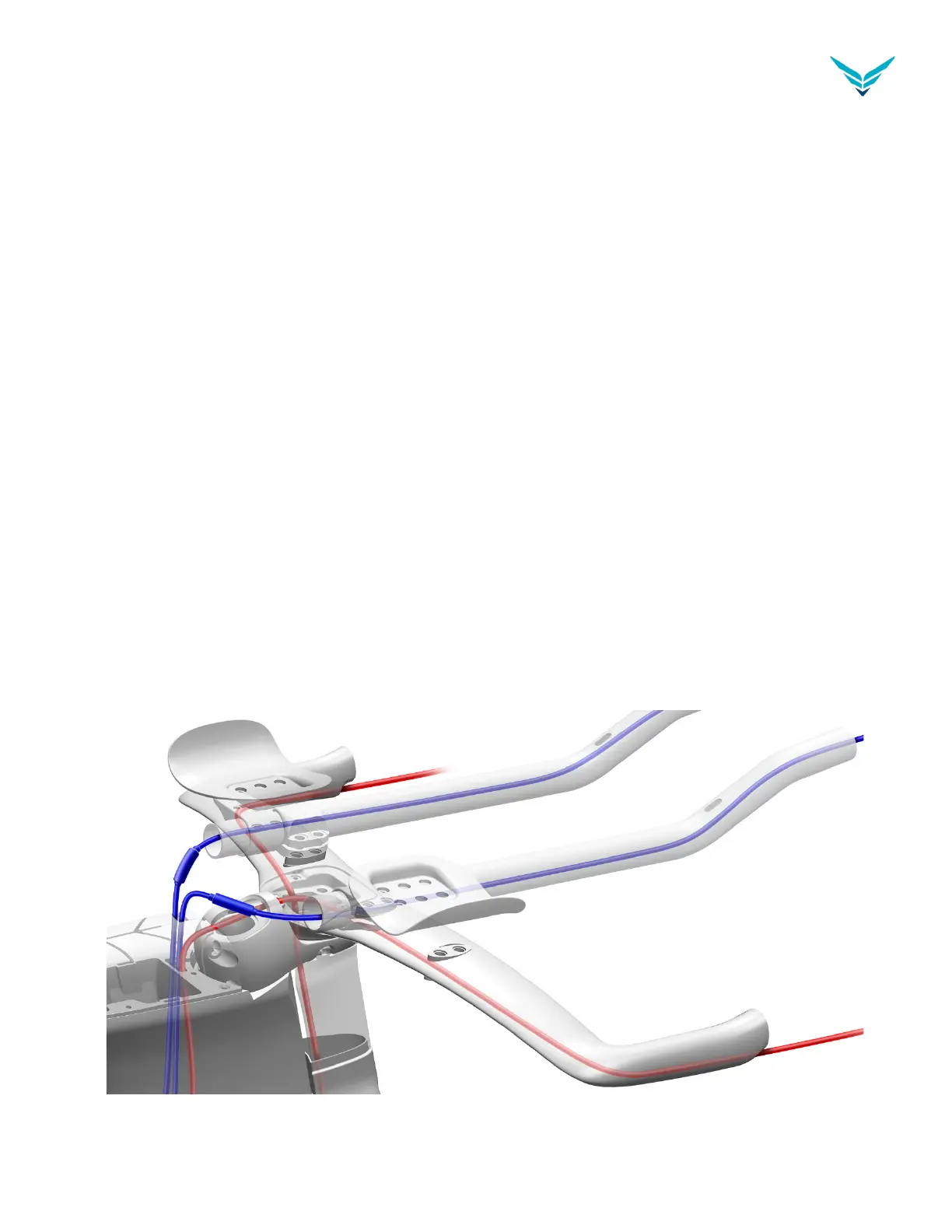
STEP 2
After cutting the necessary lengths of housing, route the two housing pieces through the extensions.
See Figure D2. Insert the ends of the housing lengths into micro adjusters.
Figure D2