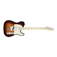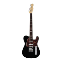
Do you have a question about the Fender Deluxe Nashville Tele and is the answer not in the manual?
Solder white wire from bridge P.U. to 5-way switch.
Solder yellow wire from middle P.U. to 5-way switch.
Solder white wire from neck P.U. to 5-way switch.
Solder black wires from pickups, red wire from middle pickup and battery to control housing.
Install shrink-tube over piezo-cable before soldering to powerchip.
Strip piezo-shield to allow 1/4" insulator on lead wire and solder shield to ground-pad.
Solder red wire from battery compartment to +9v pad on power chip PCB.
Details on acoustic pickup for each bridge section.
Shows connections for the bridge section, N.T.S.
Terminal detail of the output jack, bottom view: N.T.S.
Solder wires from battery compartment and powerchip to output jack terminals.
