May 2001 1-2 74-200016-001
FenwalNET 2000
TM
R
SILENCE
SUPERVISORY
TROUBLE
SCROLL
RESET
PRE-ALARM
ALARM
POWER ON
System Status
ACKNOWLEDGE
SILENCE
7
0
89
1
4
23
56
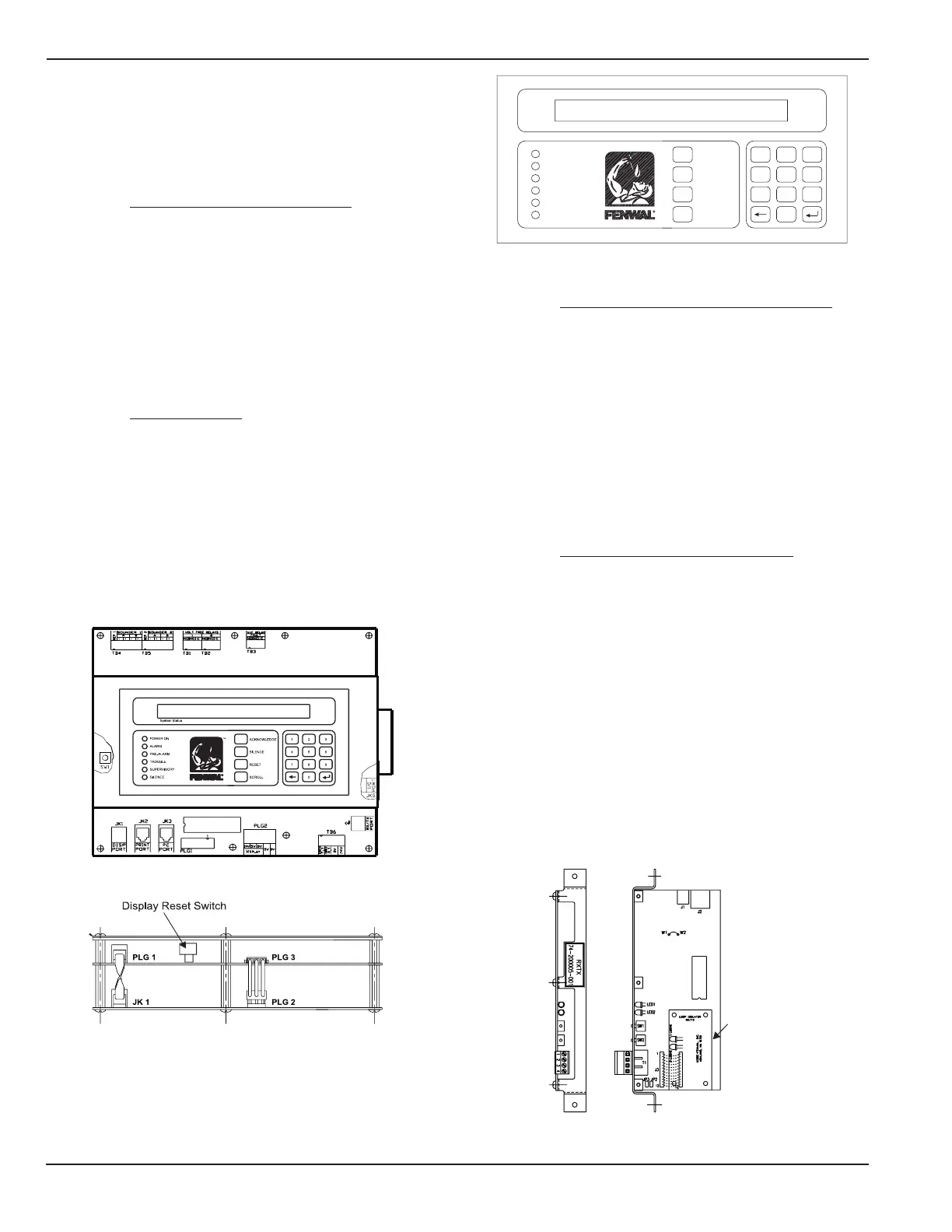
Figure 1-3. Display Module Assembly
1-2.3 Receiver/Transmitter Module (RX/TX)
The RX/TX functions as the hardware and software in-
terface between the field devices and the CCM. The RX/
TX receives control requests from the CCM and estab-
lishes communications with the field devices. The RX/
TX receives status changes from the field devices and
reports these changes to the CCM. The RX/TX shown in
Figure 1-4 is capable of communicating with up to 255
intelligent devices and complies with the wiring require-
ments of NFPA Style 4, 6 and 7 (with the use of the loop
isolator device). Style 4 initiation circuit wiring will per-
mit T tapping or branch circuitry.
1-2.4 Power Supply/Charger Assembly
The power supply/charger assembly (P/N 74-200009-
010) is comprised of a printed circuit board (PCB)
assembly and a AC/DC switching power supply unit.
The switching power supply unit provides 4 Amps of
24 Vdc power from the 120/240 Vac input power. The
PCB assembly is a microprocessor based unit which
provides the system with:
Battery charging and supervision
AC power supervision
24 Vdc supervision
Battery load test
24 Vdc ground fault detection (+/-)
Auxiliary 24 Vdc outputs
Loop Isolator
for Style 7
Figure 1-4. Receiver/Transmitter Module (RX/TX)
1-2 COMPONENT DESCRIPTION
The following paragraphs give a brief description of each
components used in the FenwalNET 2000 system. For
functional descriptions of each component, see Chapter
3 of this manual.
1-2.1 Central Control Module (CCM)
The CCM assembly, Figure 1-2, is the heart of the sys-
tem and is comprised of two PCB assemblies, the dis-
play module and the main processor module. The CCM
controls the operation and supervision of all the sys-
tem modules and software within the FenwalNET 2000
system. It receives loop device data from the RX/TX
module, processes the data based on pre-programmed
instructions and transmits output commands to the
output modules, field devices and display module(s).
1-2.2 Display Module
The display module assembly (Figure 1-3), which is at-
tached to the main processor PCB, provides the system
with the operator interface for control switches, system
status LEDs, system trouble/alarm buzzer, an 80-char-
acter (2 x 40) LCD display and an integral numeric key-
pad. The keypad is used for entering the security
password and navigating through the user menus. The
system buzzer provides two distinctly different signal-
ing patterns for audible warning of system alarms and
troubles.
Figure 1-2. Central Control Module (CCM)
 Loading...