8
EN
it is running but not actually doing the job, may
significantly reduce the exposure level.
Protect yourself against the effects of vibration by
maintaining the tool and its accessories, keeping
your hands warm, and organizing your work
patterns.
Description
The numbers in the text refer to the diagrams on
pages 2-4
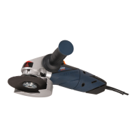
Fig. A
1. Spindle lock button
2. Release lever for protection guard
3. Protection guard
4. Release lever for On/Off paddle switch
5. On/Off paddle switch
6. Side handle connection point
Fig. B
7. Spindle
8. Side handle
9. Mounting flange
10. Wheel disc (not included)
11. Clamping nut
12. Spanner
Fig. C1
Protection guard for grinding
2. Release lever for protection guard
3. Protection guard
Fig. C2
Protection guard for cutting (not included)
2. Release lever for protection guard
3. Protection guard
Fig. D1
Protection guard for grinding
Fig. D2
Protection guard for cutting (not included)
Assembly
Before assembly, always switch off the
machine and remove the mains plug from
the mains.
Assembling the protection guard
(Fig. C and D)
(7) facing upwards.
machine head as shown in Figure C making
sure the ridges on the protection guard fall into
the notches of the machine head.
shown in Figure D and clench the release lever
for protection guard (2).
guard by releasing the lever (2), adjust the
guard to the desired position and clench the
lever to lock it.
Never attempt to remove the guard.
Mounting and removing the wheel disc
(Fig. B)
machine with diameter Ø 115 mm for
AGM1060S and Ø 125 mm for AGM1061S
and a bore from 22.2 mm the thickness of the
wheel disc should be 6 mm for wheel disc for
grinding and 3 mm for wheel disc for cutting,
the mounting wheel disc may not touch the
safety guard.
Mounting
protection guard (3) facing upwards.
firmly tighten the clamping nut (11) onto the
spindle (7) by using the spanner (12).
Removing
protection guard (3) facing upwards.
loosen the clamping nut (11) using the spanner
(12).
(7).
firmly tighten the clamping nut (11) using the
spanner (12).
 Loading...