12 ferrismowers.com
Safety Interlock System Checks
WARNING
DO NOT operate machine if any safety interlock or safety
device is not in place and functioning properly. Contact
your dealer immediately for assistance. DO NOT attempt to
defeat, modify, or remove any safety device.
TEST 1 - Engine must not crank if:
• PTO switch is engaged, OR;
• Parking brake is not engaged, OR;
• Ground speed control levers are not locked in their
NEUTRAL positions.
TEST 2 - Engine should crank if:
• PTO switch is not engaged, AND;
• Parking brake is engaged, AND;
• Ground speed control levers are locked in their
NEUTRAL positions.
TEST 3 - Engine must shut off if:
• Operator rises off seat with PTO engaged, OR
• Operator rises off seat with parking brake disengaged.
• Operator moves ground speed control levers out of their
neutral positions before disengaging parking brake.
TEST 4 - Check mower blade stopping time:
Mower blades and mower drive belt should come to a
complete stop within seven (7) seconds after electric PTO
switch is turned off (or operator rises off seat). If mower drive
belt does not stop within seven (7) seconds, see your dealer.
Note:Once the engine has stopped, PTO switch must be
turned off, parking brake must be engaged, and the ground
speed control levers must be locked in the NEUTRAL position
after the operator returns to the seat in order to start the
engine.
Features and Controls
Control Functions and Locations
The information below briefly describes the function of
individual controls. Starting, stopping, driving, and mowing
require the combined use of several controls applied in
specific sequences. To learn what combination and sequence
of controls to use for various tasks see the Operation section.
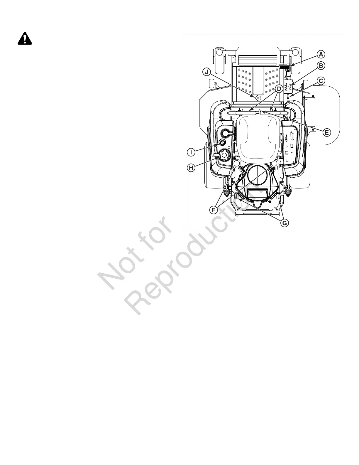
Zero-Turn Rider Controls
4
A. Deck Lift Pedal
B. Cutting Height Adjustment Pin
C. Deck Lift Lock Lever
D. Ground Speed Control Lever
E. Seat Adjustment Levers
F. Transmission Oil Fill / Tanks
G. Transmission Release Levers
H. Fuel Tank Cap
I. Fuel Level Gauge
J. Removable Floor Plate
Deck Lift Pedal, Cutting Height Adjustment Pin, and Deck
Lift Lock Lever:These controls are used to adjust the cutting
height of the mower deck.
Depress the deck lift pedal (A, Figure5) until the deck lift lock
lever (B) locks the mower deck into the 4-1/2" (11,43 cm)
TRANSPORT position. Place the cutting height adjustment
pin (C) into the hole for the desired cutting height. Depress
the deck lift pedal, move the deck lift lock lever outwards,
and slowly release the deck lift pedal until it rests against the
cutting height adjustment pin.
 Loading...