Radar Training System, LabVolt Series
© Festo Didactic 10
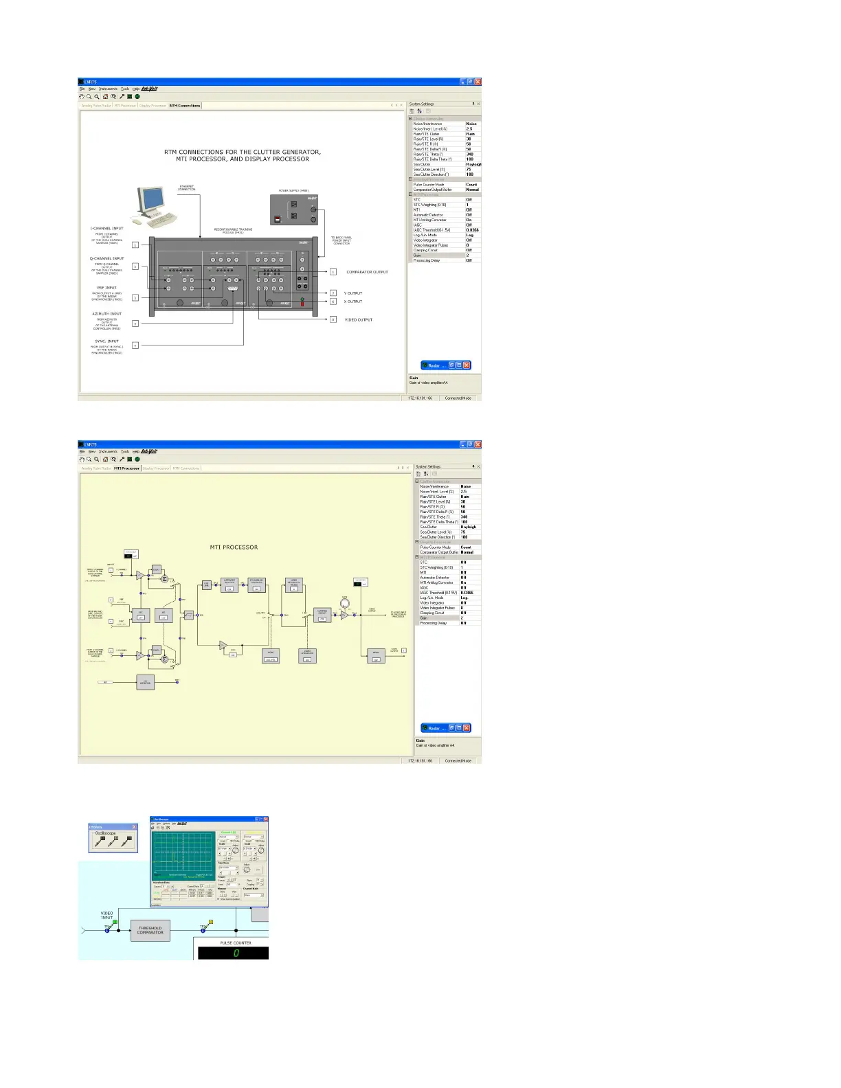
Figure 5. Window showing the interconnections to the RTM.
Figure 6. On-screen block diagram of the Moving Target Indicator (MTI)
processor.
Figure 7. Real signals can be observed on the built-in oscilloscope by
connecting virtual probes to test points in the on-screen block diagrams.


 To Next Page