Radar Training System, LabVolt Series
© Festo Didactic 14
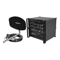
Radar Tracking Training System (Level 4, add-on to Level 3)
8112501 (8097-30)
The Radar Tracking Training System adds on to the pulse radar
implemented with the Basic Radar Training System and the
Radar Processor/Display (systems 8097-1 and 8097-2,
respectively), to form a continuous tracking radar. This radar can
track a passive target that moves in the classroom laboratory.
The Radar Tracking Training System includes an interface module
to be installed in the RTM of the Radar Processor/Display, a
special dual-feed parabolic antenna, a joystick-type hand
controller, a set of accessories, and a student manual.
The tracking radar can operate in three different modes (Scan,
Manual, and Lock), which are selected through the hand-controller buttons. In scan mode, the antenna rotates
at constant speed, allowing observation of targets on the PPI display. In manual mode, the operator can isolate
a fixed or moving target of his or her choice, using the hand controller to control the antenna beam angle and to
position an electronic marker (range gate) over the target echo signal. A computer-based O-scope display is
used to monitor the position of the range gate relative to the echo signal of the target to be acquired. When the
range gate straddles the target echo signal, the lock mode can be activated and the target is automatically
tracked in range and azimuth by the system.
Range tracking is achieved by means of the split range-gate technique, whereas angle tracking is accomplished
using lobe switching (sequential lobing). In addition to the fully automatic tracking mode, several useful ECCM
features are available, such as a switchable lobing rate, a range tracking rate limiter in the range loop, manual
control of either the range loop or the azimuth loop while the system is locked onto a target, and leading-edge
range tracking. The computer-based interface of the tracking radar allows control of these functions and offers
the same other possibilities as for the pulse radar system (visualization of the system's block diagrams,
connection of virtual probes in the onscreen block diagrams, observation of signals on the built-in oscilloscope,
fault insertion, etc.)
List of Equipment
Qty Description
Model
number
1 Dual Feed Parabolic Antenna ______________________________________________________ 581937 (9604-A0)
1 Radar Target Tracking Interface ___________________________________________________ 8112778 (9633-10)
1 Accessories for 8096-3 ___________________________________________________________ 581984 (9690-B0)
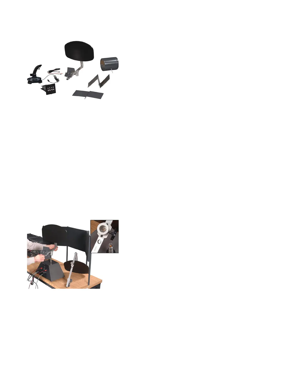
Figure 12. Antenna replacement is quick and easy thanks to miniature plug-in
connectors in the antenna frame and antenna pedestal's shaft.
Installation of the Radar Tracking
Training System is very simple: insert
the interface module in the RTM,
modify a few connections, connect the
hand controller to a USB port of the
host computer, and replace the
conventional parabolic antenna with
the dual-feed parabolic antenna.
These two antennas come with a
miniature plug-in connector to
facilitate replacement, as shown in
Figure 12.


 To Next Page
 Loading...