Radar Training System, LabVolt Series
© Festo Didactic 26
Parameter Value
Net Weight
Radar Synchronizer / Antenna Controller
595986 (9602-20)
The Radar Synchronizer / Antenna Controller is used for Pulse Repetition Frequency (PRF) generation and
synchronization of the radar system. It also controls the operating parameters of the radar antenna.
The synchronizer includes a PRF generator equipped with push buttons to select the PRF and either single or
staggered mode. Two sets of outputs are used for synchronization, one at the selected PRF and one at 1024
times the selected PRF.
The antenna controller provides three control modes for the radar antenna: manual mode, where speed
(clockwise or counterclockwise) is manually controlled; PRF locked mode, which synchronizes the rotation of
the antenna to the system PRF; and SCAN/TRACK mode for 120-degree scanning. A three-digit display that can
be switched to show antenna position or speed is provided. The controller accepts feedback signals from the
encoder on the rotating antenna pedestal and generates a command signal for output to the antenna motor
driver. The controller also generates azimuth information required by other system modules.
Unregulated dc power is automatically supplied to the Radar Synchronizer / Antenna Controller through self-
aligning connectors when it is installed on the Power Supply / Antenna Motor Driver.
Specifications
Parameter Value
Radar Synchronizer
PRF 12, 18, 144, 216, 288 Hz
Mode Single, Staggered
Outputs A & B TTL
Antenna Controller
Antenna Rotation Speed Range 0 to 15 r/min.
Azimuth Output 10-bit TTL
Output Voltage Range -15 to +15 V max.
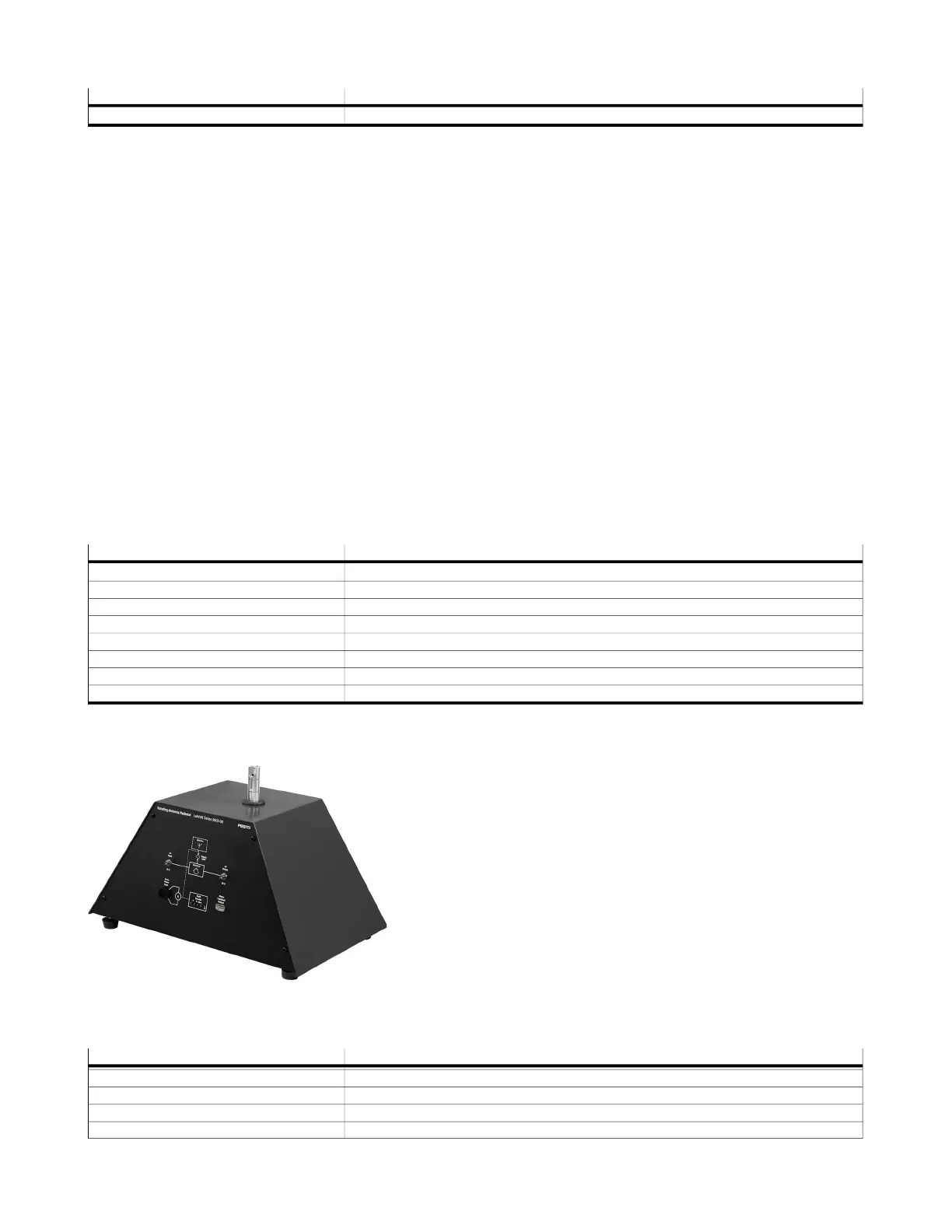
Rotating-Antenna Pedestal
8112383 (9603-10)
The Rotating-Antenna Pedestal is the mount and drive motor for
the radar antenna. It provides the RF connection between the
antenna and the radar transmitter and receiver. Antenna position
feedback is obtained from an incremental optical shaft encoder,
the output of which may be monitored through front-panel test
points. The RF section includes a circulator for simultaneous
transmission and reception. A rotary joint provides RF coupling
to the rotating antenna mount.
Specifications
Parameter Value
Power Requirement +25 V – 425 mA; -25 V – 325 mA
Rating
Input Frequency Range 10 Hz - 10 MHz, 10 MHz - 200 MHz
Input Period Range 0.1 s – 4 µs (10 Hz-2.5 MHz)
 Loading...