Festo SPC11−... 0404a Deutsch 9
4 Elektrische Installation
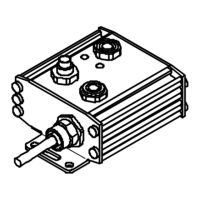
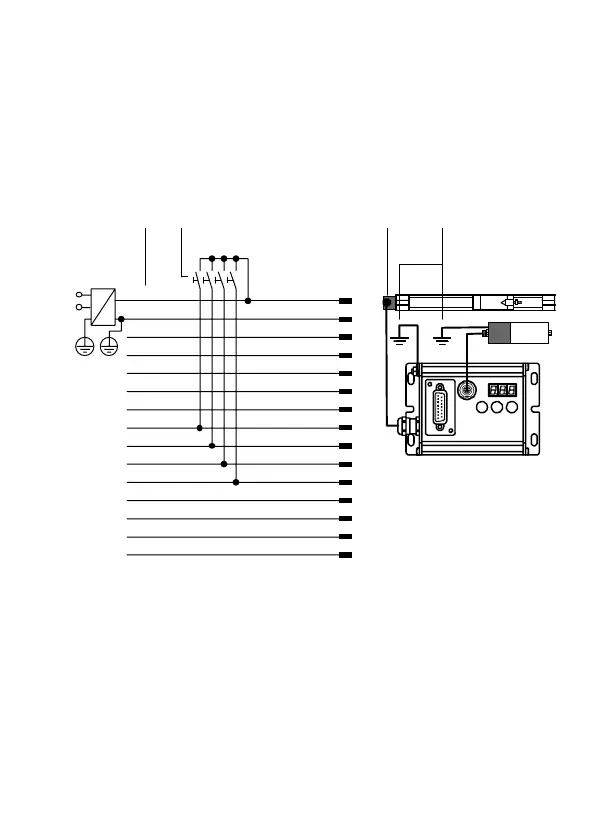
Beispiel für elektrische Installation mit Antrieb Typ
DGP(L)−... und Mess−System Typ MLO−POT−...−TLF. Nur die
angegebenen Originalkabel verwenden.
24 V
0 V
A1: P.01
A2: P.02
A3: P.03
A4: P.04
*)
A5: Error
*)
E1: P.01
E2: P.02
E3: P.03
E4: P.04
*)
E5: +/}
E6: Enter/Teach/Esc
E7: {/
E8: Remote
15
14
13
12
11
10
9
8
7
6
5
4
3
2
1
weiß−gelb
braun−grün
weiß−grün
rot−blau
grau−pink
violett
schwarz
rot
blau
pink
grau
gelb
grün
braun
weiß
12 3 4
*)
Die Funktion dieses Ein−/Ausgangs ist konfigurierbar
(siehe Systembeschreibung P.BE−SPC11−SYS−...)
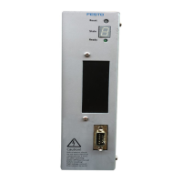
1 Pin−Belegung für Anschluss
Control mit Adernfarben für
Kabel KMPV−SUB−D−15−...
A..: Ausgang, E..: Eingang
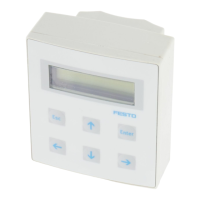
2 Taster für Fahrt zu den
Positionen
3 Endlage 1 liegt bei Linear−
antrieben auf der Seite mit
dem elektrischen Anschluss
des Mess−Systems
4 Erdung
 Loading...