Warning..................................................
For electrical isolation of operating voltage:
• Use only power units which guarantee reliable
electrical isolation of the operating voltage as per
IEC/DIN E N 60204-1. Observe also the general
requirements for PELV power circuits as per IEC/DI N
EN 60204-1.
Switch power packs are permitted, providing they
guarantee reliable isolation in accordance with
EN 60950/VDE 0805.
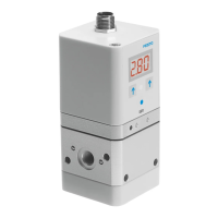
1 Supply port (1)
2 Electrical connection
3 Status LED (green)
4 Earth terminal, external (front and back side)
5 Operating key upwards (UP)
6 LED display
7 Operating key downwards (DOWN)
8 Edit key
9 Pressure output (2)
aJ Venting (3)
aA Front fastening hole
aB Side fastening hole
1
2
3
5
6
4
7
8
9
aJ
aA
aB
1
aB
2
6
65
7
9
aJ
aA
4
4
Type: ...E1T
Type: ...E1
8
3
Fig. 1
Proportional pre ssure regulating valve en
..................
Note.......................................................
• Installation and commissioning may only be
performed in accordance with the operating
instructions and by qualified personnel.
1 Application and function
The VPPE-... is designed to control pressure propor tion-
ately to a specified setpoint value.
Replacement of manually adjustable pressure regulators
by remotely, electrically adjustable regulators, to have
different machine parameters available quickly and auto-
matically, for example.
Supply port
Setpoint value
Setpoint value
Pressure
output
Venting
Pin 5
2 Variants of the VPPE-...
Type code of the VPPE-...
VPPE-3- 1-1/8-6-010-E1T
12
3
Item Features Meaning
1
Pressure regulation range:
2
6
10
0.02 … 2.0 bar
0.06 … 6.0 bar
0.1 … 10.0 bar
2
Setpoint specification:
010
420
0 … 10 V (voltage)
4 … 20 mA (current)
3
Control unit: E1
Type o f mou n t in g : T
7-segment LED display
Supply manifold mounting
3 Conditions of use
General conditions for the correct and safe use of the
product, which must be observed at all times:
• Observe the specified limits (e.g. for pressures,
temperatures and electric voltage).
• Makesurethereisasupplyofcorrectlyprepared
compressed air in accordance with the specifications on
the medium Technical specifications.
• Please observe the prevailing ambient conditions.
• Please comply with national and local safety laws and
regulations.
• Remove all transport packing, such as protective wax,
foils, caps, cardboard boxes (with exception of the
covers in the pneumatic connections).
The individual materials can be stored in containers for
recycling purposes.
• Slowly pressurize the complete system.
This will prevent uncontrolled movements from
occurring.
• Note the warnings and instructions
–ontheproduct
– in these operating instructions.
• Use the product in its original state without undertaking
any modifications.
4 Fitting
4.1 Mechanical
• Handle the VPPE-... with care so that the electrical
connection is not damaged.
Such damage reduces the operational reliability.
• Make sure there is sufficient space for the cable
connection and tube couplings. This avoids breakage of
the connecting cable.
• Put the VPPE-... as close as po ssible to the consuming
device. This leads to improved control precision annd
shorter response times.
• Push two screws (M4) into the side mounting holes aB
or the front mounting holes aA (see Fig. 1),
max. torque: 2 Nm.
• Fasten the VPPE-... in the intended location.
4.2 Pneumatic
• Remove the c overs on the compressed air connections.
• Attach the pneumatic tubing to the following connec-
tions (see Fig. 1):
– Supply port (1) 1
– Pressure output (2) 9
• Install a silencer at venting (3) (item aJ )orremovethe
exhaust with ducted tubing.
Note.......................................................
The position of the pneumatic connections depends on
the variant ordered.
4.3 Electrical
Note.......................................................
Make sure that the cable is laid as follows:
– not squashed
–notbent
–notstretched.
• Use accessories from Festo (see “Accessories”):
– plug socket with cable
or
– socket cable, ready-to-use.
This ensures that the specified protection class IP65
and E MC are achieved.
Note......................................................
To ensure EMC safety, the device must be ear thed as
follows:
• Use the ear th terminal (see Fig. 1).
• Use the f ollowing ear thing accessories (included in
delivery):
– Self-cutting screw
– Flat plug
–Contactdisc
• Connect the circuitry of the VPPE-... as show in the
circuit diagram. Preferably use cable from Festo.
1
2
5
4
PIN no. Colour
1)
VPPE
1 brown +24 VDC
2 white Analogue input – setpoint value / – w
3 blue GND
4 black Analogue input + setpoint value / + w
(0 … 10 V or 4 … 20 mA)
5 grey Switch output (24 V) or
analogue output (0 … 10 V or 4 … 20 mA)
+ actual value / X
OUT
1)
Colour is o nly valid for accessory cable from Festo
5 Commissioning
Note......................................................
• The V PPE-... interprets setpoint signals less than
0.1 V as 0 V and setpoint signals less than 4.16 mA
as 4 mA. In t his case, the output pressure is set to
0 bar through activation of the ventilation valve.
Asaresult,aclearvalveconditionisassuredat
w=0.
• Safety position:
In case of setpoint cable break of the voltage variant,
the output pressure is set to 0 bar. In case of setpoint
cable break of the current variant, or in case of loss
of power supply, the output pressure remains uncon-
trolled. Leakage produces a change in pressure in the
long term.
• Connect the VPPE-... with a setpoint signal.
The VPPE has a so-called “diffe rential input”. The
setpoint signal is applied to the contact Pin 2 and Pin 4,
whereby the lower potential must be connected to
contact Pin 2 and the higher potential to contact Pin 4.
Contact Pin 2 (– setpoint) can be connected to contact
Pin 3 (GND).
• Apply current to the VPPE-... with direct current
(Supply voltage U
V
=24VDC±10%).
• Pressurise the VPPE-... with a supply pressure (p1) at
least 1 bar higher than the maximum desired output
pressure. A proportional output pressure (p2) is set
automatically.
The following output pressure range is then assigned to
the setpoint signal range 0 … 10 V or 4 … 20 mA:
Setpoint
Output pressure range of the variant
e
2bar 6bar 10 bar
0…10Vor
4…20mA
0.02 … 2 bar 0.06 … 6 bar 0.1 … 10 bar
5.1 Recommended parameter sets
The valves in all pressure variants are set at the factory
with Preset 2.
Preset
Preset
recommendation
1 2 3
Consuming device vo lumes <0.5l ~0.5l >0.5l
5.2 VPPE display and meaning
Notes on the following table:
Preset, control behaviour:
You can select the desired fact ory parameter set in the
menu on the VPPE (Pr1, Pr2, Pr3).
Dis-
play
Meaning Description
[An] Analogue Output: Analogue
[bAr] bar Pressure unit
[Eco] ECO mode Display switch-off (adjustable)
[Frc] Force Manual setpoint input
[HY] Hysteresis Spread, switch difference
[in] Setpoint value When key is pressed (1 sec.), [in]
appears. When the key is released,
the setpoint value is displayed.
[Loc] Lock Input blocked with Pin code
[n.Hi] Switch normally
closed
Contact (normally closed)
[n.Lo] Switch normally
open
Contact (normally open)
[OFS] Offset Zeropointlift(outputpressure
withoutsetpointvalue)
[out] Actual value When key is pressed (1 sec.), [out]
appears. When the key is released,
the actual value is displayed.
[PA] Kilo pascal Pressure unit (in KPa !)
[Pin] Pin code Enter value for locking (1 … 999)
[Pr1] Preset 1 (see section 5.1)
[Pr2] Preset 2 (see section 5.1)
[Pr3] Preset 3 (see section 5.1)
[PSi] psi Pressure unit
[rES] Reset
(factory setting)
Switch on device with pressed
+ + Edit keys. Observe the
instruction in chapter 10.
[rnG] Range Pressure range adjustment
[Snr] Display series
number
Switch on device with pressed
+ Edit keys: Series number is
displayed to 6 places, first [xxx.] than
[xxx], alternating approx. 2 sec.
[SOF] Display software
version
Switch on device with pressed
+ Edit keys: Software version
appears
[SP] Switching point (see section 5.3)
[SP.H] Switching point high Top switching point (see section 5.3)
[SP.L] Switching point low Bottom switching point
(see section 5.3)
[SP.O.] Set point ok Setpoint value reached
(see section 5.3)
[unL] Unlock Lock removed
Threshold value
comparator
(see section 5.3)
Window comparator (see section 5.3)
[._..] ECO mode activated After x seconds (adjustable), a line
moves through the display [._..]
VPPE-3-1-1/8-...-E1
(LED-Display)
Operating instructions
Original: de
Festo AG & Co. KG
Postfach
D-73726 Esslingen
Phone:
+49/711/347-0
www.festo.de
0909a 749 698