All metric screws need to be secured
with thread lock fluid.
7080/3
6069/2
8600/13
8600/3 8600/4
8602/1
8493
8600/11
8602/2
8600/13 8600/13
8602/2
8600/2
8600/13
8600/9
8600/10
8493
6924/20
6069/2
7080/3
6924/20
8600/8
6067
6068
8500/3
6067
8600/8
8600/11
8600/1
8600/11
8600/6
Steel gearwheel
large 48t.
Screw M4x8
Flat side
O-ring
Ball diff.
axle
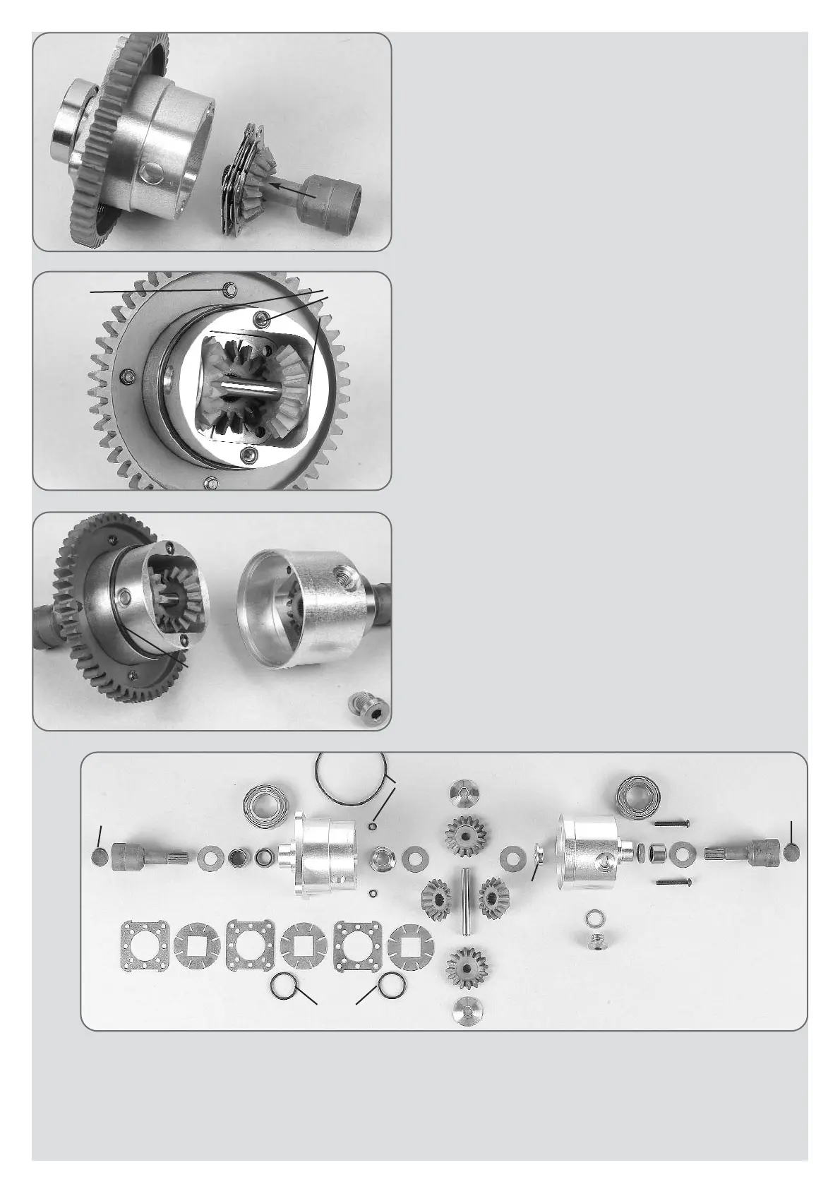
Assembly
The flange bushes 8602/2, roller bearing 8602/1 as well as the rotary shaft se-
als 8600/6 and the ball bearing 8493 have professionally been mounted on
the alloy differential housing A/B by the manufacturers FG .
Now mount the steel gearwheel 48 teeth on the alloy differential housing A.
Check the internal and external fins on production birs, if necessary remove
them with an emery cloth. Do not bend the fins.
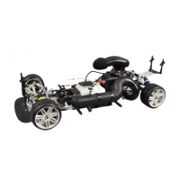
Now mount the set of fins according to illustration 1: Insert a differential ge-
arwheel with square on a differential bevel wheel axle. Then slide on the
square one after another in the following order 1x internal fin, 1x O-ring 14x1.5,
1x external fin, 1x internal fin, 1x O-ring 14x1.5, 1x external fin, 1x internal fin,
1x external fin. Grease the shim ring 8600/13 a little and put the differential
housing on the flange bush 8602/2. Now insert the whole package into the
differential housing A according to the illustration. Now push the differential
gearwheel with a screw driver with the fin package towards the housing and
carefully pull out the differential axle.
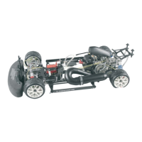
Push both bronze bushes 8600/8 from the inside to the outside into the bo-
rings of the differential housing, position 1a. Insert the differential gearwheels
B into the housing and push in the differential bevel differential gear axle
6068. Grease the 8mm shaft of the ball diff. axle 6069/2 plentifully and push
it from outside into the differential housing. The borings of the alloy diffe-
rential housing need to align with the borings of the differential gearwheels.
If the borings are offset, the gearwheels need to be disassembled and reas-
sembled once again displaced by one tooth until the parts can be easily tur-
ned. Mount the O-rings 3x1 and 42x1.5 according to the illustration.
Now join the two halves of the housing, check them for free movement and
assemble them using the two enclosed M3x20 screws.
Fill in about 15ml of the enclosed silicon oil into the boring of the alloy diffe-
rential housing B. Add about 5ml 2-stroke engine oil for better lubrication. Then
close the boring by means of the locking screw M8x1/ copper disk. You may
influence the locking effect by the number of fins by the viscosity of the fil-
led in oil as well as by the filling quantity.
When driving an overpressure is building up in the diff. housing. Therefore you
should unscrew the locking screw after a few laps of driving time in order to
release the overpressure.
Insert the fin package
into housing A.
O-ring 42x1,5
O-ring 3x1
Bronze bush
7x18x5
Position 1
Parts are in
bag C
Position 1b
Parts are in
bag C
Position 1a
Parts are in
bag C
 Loading...