Do you have a question about the FG Wilson PowerWizard 1.1 and is the answer not in the manual?
Overview of the PowerWizard controller and its intended audience.
Describes the wide range of applications for PowerWizard controllers in generating set systems.
Lists features of PowerWizard 1.1, 1.1+, and 2.1 versions.
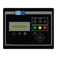
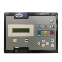
Details the physical components and labeling of the PowerWizard control panel.
Explains the function of the AC Overview, Engine Overview, and Main Menu keys for navigation.
Describes the function of the RUN, AUTO, and STOP keys for engine operation modes.
Details the function of Scroll Up, Escape, Scroll Right, Enter/OK, Scroll Down, and Scroll Left keys for menu interaction.
Explains the function of warning lights, alarm acknowledge, event reset, event log keys, and emergency stop.
Illustrates the menu structure for PowerWizard 1.1, 1.1+, and 2.1 models.
Covers engine starting and stopping sequences, event system, and event states.
Describes methods for viewing events in the active events menu.
Provides a procedure for resetting individual events after fault rectification.
Outlines a simplified process for resetting all events across all modules.
Explains the 3 levels of password protection for setpoint adjustments and access control.
Details how to set the time, date, and format for event logging and auto control.
Describes how to use the PowerWizard to prime engines with electronic fuel lift pumps.
Explains how to control fuel transfer operations using the PowerWizard.
Details the PCT feature for programming timed tasks and outputs for generating sets.
Specifies the DC voltage requirements and power considerations for the PowerWizard controller.
Provides guidelines for selecting a suitable mounting location for the PowerWizard control.
Details the electrical connections for PowerWizard 1.1 & 1.1+ using the 70-pin connector.
Shows connection diagrams for different generator winding configurations (Star, Delta).
Explains how to connect external potential transformers for voltage monitoring.
Introduces the supported data links (J1939, SCADA) for communication.
Details the Primary J1939 Data Link, its protocol, and hardware requirements for communication.
Explains the Accessory J1939 Data Link for PowerWizard 2.1, used for annunciators and expansion modules.
Introduces optional modules like the CAN Annunciator and their support.
Describes the CAN Annunciator for displaying alarm and status indications.
Explains how PowerWizard supports the Annunciator via CAN1 and CAN2.
Covers the purpose and configuration of digital inputs for monitoring and control functions.
Details the function of the Emergency Stop and Remote Initiate dedicated digital inputs.
Explains programming options for digital inputs: Command/Status, System Events, SCADA Datalink.
Describes the types of relays and digital outputs and their configuration options.
Details how to program analogue inputs for various parameters using resistive or voltage senders.
Information on the Electronic Service Tool (EST) for servicing and its licensing.
Explains the types of files (.fls, .xml) used for updating controller software and configuration.
Lists common EST error messages and troubleshooting steps for connectivity and compatibility.
Explains how to enable and use the Reduced Power Mode via EST or keypad for power saving.
Covers resetting, changing duration, and disabling the service maintenance interval warning.
Describes how to select between Technical English and Customer Language.
Details how to disable the "Not In Auto" warning for specific applications.
Explains how to disable the Thermo Start feature by setting the activation time to 0.
A comprehensive list of Suspect Parameter Numbers (SPN) and Failure Mode Identifiers (FMI) for events.
Lists setpoints for controlling the automatic start and stop sequence of the engine.
Details setpoints for configuring the Automatic Voltage Regulator (AVR) desired voltage.
Lists setpoints for configuring the governor's desired engine speed.
Covers setpoints for monitoring battery voltage, including warning and shutdown thresholds.
Details setpoints related to the engine's crank and start counter functions.
Lists setpoints for engine speed monitoring, including shutdown and warning thresholds.
Covers setpoints for enhanced engine monitoring features like cylinder temperature and cylinder count.
Details setpoints for configuring service maintenance intervals in hours and days.
Lists available event response selections for warnings, shutdowns, and trips.
Covers setpoints for enhanced generator monitoring like winding temperature and bearing sensors.
Details setpoints for AC monitoring including connection configuration, transformer ratings, and poles.
Explains the AC power monitor for kW, kWh, kVAr, and kVA measurements.
Lists setpoints for generator over current protection, including warning and shutdown thresholds.
Details setpoints for generator over and under frequency protection.
Covers setpoints for generator over and under voltage protection.
Lists setpoints for generator reverse power protection.
Details setpoints for configuring the reduced power mode delay time.
Refers to the Digital Inputs section for details on input configuration.
Refers to the Relay and Digital Outputs section for details on output configuration.
Refers to the Relay and Digital Outputs section for details on output configuration.
Explains analogue inputs and lists setpoints for type, range, and event thresholds.
| Brand | FG Wilson |
|---|---|
| Model | PowerWizard 1.1 |
| Category | Control Panel |
| Language | English |