EasyManua.ls Logo

Fiat 411 Rb - Page 24

Fiat 411 Rb
27 pages
Print Icon
To Next Page IconTo Next Page
To Previous Page IconTo Previous Page
Loading...
sreznms
corvmor.
ADJUSTMENT
if
after
tong
use
the
steering
wheel
piay
has
become
excessive,
adjust
by
tightening
as
required
the
screw
on
steering
box
(fig.
29).
Should
this
prove
insufficient
to
take
up
the
steering
wheel
play,
check
the
play
in
worm
screw
roiier
bearings
and
adjust
by
removing
one
or
more
of
the
shims
mounted
betweentthe
box
and
its
upper
coven
GENERATOR
/mo
STARTER
MOTOR
To
check
generator
brushes
and
commutator,
remove
both
heads;
for
the
starter
motor
it
is
sufficient
to
remove
the
cover
band.
To
lubricate
the
generator
bearings
(operation
to
be
performed
every
1200
working
hours)
remove
the
heads
and
pack
with
Fiat
Jota
3
grease.
On
the
contrary,
the
starter
motor
needs
no
periodic
lubrication.
Only
when
overhauling
the
motor
pack
the
free
wheel
with
Fiat
Jota
2/M
grease.
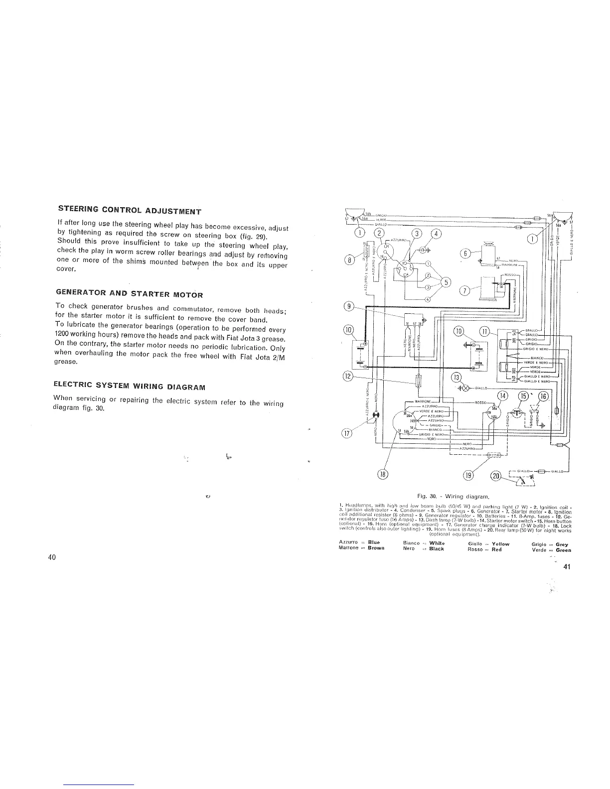
ELECTREC
SYSTEM
WIRING
DIAGRAM
When
servicing
or
repairing
the
electric
system
refer
to
the
wiring
diagram
fig.
30.
I-.
4
1"
,_.
‘(J
40
iwi“
_
55b
1
§\_:w
5“
emf-I0
—-—-
-'
—~
—~-~
~
"
"W
'
fi
i
5;
5;
gr;
SE-a
-_,;_n[;[__
_
..r__
W..-
.
.
.
.
.
_
‘
...__._-v
V
{Q}:
5“
-—
L
os.1\ar_o.
4
I
1
—
my
W
'
W
~"~
YE)"-n
/@
e
v
{Ti
GP
910
FDE
LO
£
NiRO
era
.
'L)l\
Y
,5
-
(
-qd
1;.
,_
1
§§t_____________
/'
it
i
F-e__
?
tit;
if
|t_____m__.
1.
Z
if
r"
sso
l
j
A
,___Q_
\
@~\___l_':1w_
4”“
"'
W
V
"W
V
'
"l'?_._’7
T
‘ i
*~—~.____‘n’_‘
r--»~'~**]
.
|.
swims“
i
51
57
10
i
~
-
m
emtto-A
QX
®
CA
G!/\L|.rJ:]-_¢w~--——
“'
‘
1
=1
--Gn|e|0-
i
.
____
.
'
W»
7*
cs<|(4ro._~..o,.i‘
W;
“
'
omcio
2
mino-~T‘---~.
‘__
armco
‘ ‘
'
'_'
VERDE
E
Mum
'“‘“*
W
-
Q
El
N
vsnot
—
"
'7’
‘
-
:5
vmos----¢
i
®
‘ i
1
=
er/arm
£
rvsno--l
~l
.
N-.
MAR
NE
A22
i
CZ
RE;
a
NERC
NERO
a
___j
_
.
5'
"_
""
'
.
1
.+.
;
§l‘
-._
5
+-
1
e
W
8}»
.___..».
T-en
e
1
1"‘
"‘
"Y
ca
e
04'!
-"
¢
J,-jsno-<z.£v~.E
A
"‘
GiALLO
E
NERO
‘
_.?_____>__
r;|Au.o---M
.
@
AARRONE
I .
:7
R0550
AZZURNO
;
1:
‘
20‘
VERDE
E
NERO
"
J
55.1
AZZURRO-
"'\
~-—
-
459
3|",
AZZUHHO
a
‘
-
,/
‘
\-
-—
ore:s|0~
——|
--*
_
/cs
/"4
51
gab
SB
'
Bi’f‘~CO‘"+'L-—
—
-_
V
is
—
' '
fr
Ti’!
i
Q1)
L2
.
.
<;R|G|u
E
NERO
~
—
V
e
'
—~—
W
r.1Eno—----~—“—-————~
1,
‘
__ 77
W
V
,
W
mm)
_
__,_
,
__
nzzueeno
-77;:
T‘
"CI“":l‘?'“J
{--—
6ml.|.0-
-cf§>-
0|M.l.0—-i
® ®
gjgifh
Fig.
30.
~
Wiring
diagram.
1.
'rl¢¢e;:ltile1|11£>5i
vgith
ing?
zgrd
{flow
being
1>c_i>_lF|)l:'Jr‘.*>(g_»'1:’,’;Jg\/)
llggilisgrg/:2
I-n§iOi;)[\1;510EYlgr§~ifi;gn
3.
lgni'
ion
is
ri'ui0r-
.
on
enser-.
.
.
:1
-
.
gr
>~
-
~
_
:j;(1i|]e:\(E(iil'i0n:-3!
resistor
(6
ohms)
-
9.
Generator
regulator
-
10.
tiatlerres
-
E11.
€§5fifJr—fl1§J&3:n
r!r:l’&t|()1'
H’-:t'JLJ|HiOr‘iLJ€>'(!
('16
Amns)-13-De$l'1lr1m4>(i-Vtf
tllllib)-'|4.’§3i<l‘rif3F(;fl€1it)f1>\E'\?‘6v
hung)
“
18
Lock
(optional)
-
16.
Horn
{optrorral
_equ|prm;r1l)
-
17.
G£:I|(;‘fc1i0I'
r:hart1<>_}Ilj
F?
91'
60
W)
for
mum
works
switch
(corrirofs
also
outer
lighting)
-
19.
Horn
luses
_(8
Amps)
-
20.:
ear
amp
.
t .
(options?
equipment).
.
-
»
=
Grey
AH",-,0
Bgue
Bmncg
White
Giaiio
-4
Yeitow
Grlgio
Marrone
-ea
Brown
Nero
_-:
Btack
Rosso
:=
Red
Verde E
5'69"
"
41
1

Related product manuals