Page
2
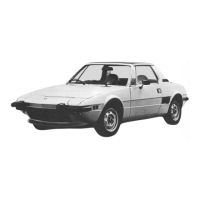
ENGINE
Engine
type
..............................................................................................
128
AS.040.4
Cycle
........................................................................................................
Four-stroke,
gasoline
No.
of
cylinders
..........................................................................................
Four
Bore
..........................................................................................................
3.39
in.
(86mm)
Stroke
........................................................................................................
2.19
in.
(55.5mm)
Displacement
.................
.
..........................................................................
78.7
cu.
in.
(1290cc)
Compression
ratio
......................................................................................
8.5
to
1
Horsepower
rating,
S.A.E.
net
....................................................................
66.5
HP
at
.........
.
....................................................................................................
6,000
rpm
Torque
rating,
S.A.E.
net
..........................................................................
671/4
ft.
lbs.
at
..............................................................................................................
4,000
rpm
Arrangement
..............................................................................................
central,
transversally
mounted
VALVE
MECHANISM
Intake
opens
..................................................................................................
10°
B.T.D.C.
Closes
..................................................................................................
54°
A.B.D.C.
Exhaust
opens
..................................................................................................
54"
8.3.0.0.
closes
..................................................................................................
10°
A.T.D.C.
Valve
clearance:
——for
checking
valve
timing
....................................................................
0.020
in.
(0.50mm)
—operation
clearance,
engine
cold:
Intake
........................................................................................................
0.012
in.
(0.30mm)
Exhaust
......................................................................................................
0.016
in.
(0.40mm)
FUEL
SYSTEM
Feeding
by
mechanical
pump.
Carburetor:
vertical,
downdraft
WEBER
32DMTRA200
with
starting
device
(vacuum-operated
butterfly
valve
choke,
accelerating
pump,
and
mechanically-controlled
opening
of
secondary
throttle.
intake
manifold
with
hot
water
header
for
mixture
pre-heating.
at
idle.
Fuel
filter
in
feed
line
from
pump
to
carburetor.
Paper
cartridge
air
cleaner
with
silencer.
LUBRICATDN
SYSTEM
Forced
circulation
by
gear
pump
and
pressure
limiting
valve.
Full-flow
cartridge
oil
filter.
Normal
oil
pressure
64
to
85
psi
(4.5
to
6
kg/cm)
at
212°
F
(100°
C).
COOLING
SYSTEM
Radiator
and
expansion
tank.
Water
circulated
by
cen~
trifugal
pump.
Controlled
by
thermostat
on
cylinder
head
outlet
duct.
Thermostat
begins
to
open
at
165°
F
to
170°
F
(73°
to
77°
C).
Four-bladed
fan,
driven
by
electric
motor.
Controlled
by
thermostatic
switch
in
radiator.
Thermostatic
switch
cut-in
about
194°
F
(90°
C).
EMISSION
CONTROL
SYSTEMS
Engine
fuel
feed
system
provided
with
fuel
recircula-
tion
(closed
circuit)
and
evaporative
emission
control
system.
Crankcase
emission
control
system
(closed
circuit)
by
recirculation
of
blow-by
gases
and
oil
vapors.
Exhaust
emission
control
system
(reduces
air
pollution
from
exhaust
gases)
separate
from
the
crankcase
emis-
sion
control
system.
 Loading...