EasyManua.ls Logo

FIBARO Smart Implant - User Manual

FIBARO Smart Implant
12 pages
Print Icon
To Next Page IconTo Next Page
Loading...
Fibaro
Smart Implant
SKU: FIBEFGBS-222
Quickstart
This is a secure Alarm Sensor for Europe. To run this device please connect it to your mains power supply.
1.Set the main controller in Security S2 Authenticated add mode (see the controllers manual).
2.Scan the DSK QR code or input the 5-digit PIN code (label on the bottom of the box).
3.Power the device.
4.LED will start blinking yellow, wait for the adding process to end.
5.Successful adding will be confirmed by the Z-Wave controllers message.
Important safety information
Please read this manual carefully. Failure to follow the recommendations in this manual may be dangerous or may violate the law. The manufacturer, importer,
distributor and seller shall not be liable for any loss or damage resulting from failure to comply with the instructions in this manual or any other material. Use this
equipment only for its intended purpose. Follow the disposal instructions. Do not dispose of electronic equipment or batteries in a fire or near open heat sources.
What is Z-Wave?
Z-Wave is the international wireless protocol for communication in the Smart Home. This device is suited for use in the region mentioned in the Quickstart section.
Z-Wave ensures a reliable communication by reconfirming every message (two-way communication) and
every mains powered node can act as a repeater for other nodes (meshed network) in case the receiver is
not in direct wireless range of the transmitter.
This device and every other certified Z-Wave device can be used together with any other certified Z-
Wave device regardless of brand and origin as long as both are suited for the same frequency range.
If a device supports secure communication it will communicate with other devices secure as long as this
device provides the same or a higher level of security. Otherwise it will automatically turn into a lower level
of security to maintain backward compatibility.
For more information about Z-Wave technology, devices, white papers etc. please refer to www.z-wave.info.
Product Description
FIBARO Smart Implant allows to enhance the functionality of wired sensors and other devices by adding Z-Wave network communication.You can connect binary
sensors, analog sensors, DS18B20 temperature sensors or DHT22 humidity and temperature sensor to report their readings to the Z-Wave controller.It can also
control devices by opening/closing output contacts independently of the inputs.Main features of FIBARO Smart Implant:- Compatible with any Z-Wave or Z-Wave+
Controller,- Supports Z-Wave network Security Modes: S0 with AES-128 encryption and S2 with PRNG-based encryption,- Allows for connecting sensors: o6
DS18B20 sensors,o1 DHT sensor, o2 2-wire analog sensor, o2 3-wire analog sensor, o2 binary sensors. - Works as a Z-Wave signal repeater,- Built-in
temperature sensor.
Prepare for Installation / Reset
Please read the user manual before installing the product.
In order to include (add) a Z-Wave device to a network it must be in factory default state. Please make sure to reset the device into factory default. You can do
this by performing an Exclusion operation as described below in the manual. Every Z-Wave controller is able to perform this operation however it is recommended
to use the primary controller of the previous network to make sure the very device is excluded properly from this network.
Reset to factory default
This device also allows to be reset without any involvement of a Z-Wave controller. This procedure should only be used when the primary controller is inoperable.
1.Press and hold the button to enter the menu.
2.Release button when the device glows yellow.
3.Quickly click the button to confirm.
4.After few seconds the device will be restarted, which is signalled with the red colour.
Safety Warning for Mains Powered Devices
ATTENTION: only authorized technicians under consideration of the country-specific installation guidelines/norms may do works with mains power. Prior to the
assembly of the product, the voltage network has to be switched off and ensured against re-switching.
Question and Answer IconNeed help?

Do you have a question about the FIBARO Smart Implant and is the answer not in the manual?

Summary

Fibaro

Smart Implant

Product name and SKU of the Z-Wave device.

Quickstart

Important safety information

What is Z-Wave?

Explains the Z-Wave wireless protocol for Smart Home communication.

Product Description

Details the functionality and capabilities of the FIBARO Smart Implant.

Prepare for Installation; Reset

Instructions on preparing the device for installation and factory reset procedures.

Reset to factory default

Step-by-step guide to reset the device to its original factory settings.

Safety Warning for Mains Powered Devices

Critical safety precautions for working with mains voltage and powered devices.

Installation

Connection with alarm line

Wiring diagrams and instructions for connecting alarm system components.

Connection with DS18 B20

Instructions for connecting DS18B20 temperature sensors to the device.

Connection with DHT22

Instructions for connecting DHT22 humidity and temperature sensors.

Connection with 2-wire 0-10 V Sensor

Guide for connecting 0-10V analog sensors using a pull-up resistor.

Connection with binary sensor or button

Instructions for connecting binary sensors or buttons to inputs.

Connection with gate opener

Specific wiring and configuration for controlling a gate opener.

Inclusion;Exclusion

Inclusion

Step-by-step process to add the device to an existing Z-Wave network.

Exclusion

Step-by-step process to remove the device from a Z-Wave network.

Product Usage

Tips for arranging the antenna

Recommendations for positioning the antenna for best signal reception.

Range Tester

Z-Wave range tester signal modes

Explanation of different visual indicators during range testing.

Visual Indications

Update

LED status meanings during firmware or software updates.

Menu

LED status meanings when navigating through the device's menu.

Activating scenes

Communication to a Sleeping device (Wakeup)

Quick trouble shooting

Association - one device controls an other device

Configuration Parameters

Parameter 20: Input 1 - operating mode

Configures the operational mode for the first input terminal (IN1).

Parameter 21: Input 2 - operating mode

Configures the operational mode for the second input terminal (IN2).

Parameter 24: Inputs orientation

Allows reversing the input logic for IN1 and IN2 without rewiring.

Parameter 25: Outputs orientation

Allows reversing the output logic for OUT1 and OUT2 without rewiring.

Parameter 40: Input 1 - sent scenes

Defines actions on IN1 that trigger sending specific scene IDs and attributes.

Parameter 41: Input 2 - sent scenes

Defines actions on IN2 that trigger sending specific scene IDs and attributes.

Parameter 47: Input 1 - value sent to 2 nd association group when activated

Sets the value sent to association group 2 upon IN1 activation.

Parameter 49: Input 1 - value sent to 2 nd association group when deactivated

Sets the value sent to association group 2 upon IN1 deactivation.

Parameter 52: Input 2 - value sent to 3 rd association group when activated

Sets the value sent to association group 3 upon IN2 activation.

Parameter 54: Input 2 - value sent to 3 rd association group when deactivated

Sets the value sent to association group 3 upon IN2 deactivation.

Parameter 63: Analog inputs - minimal change to report

Sets threshold for reporting analog input value changes.

Parameter 64: Analog inputs - periodical reports

Configures the interval for periodic analog input value reports.

Parameter 65: Internal temperature sensor - minimal change to report

Sets threshold for reporting internal temperature sensor changes.

Parameter 66: Internal temperature sensor - periodical reports

Configures the interval for periodic internal temperature sensor reports.

Parameter 67: External sensors - minimal change to report

Sets threshold for reporting external sensor value changes.

Parameter 68: External sensors - periodical reports

Configures the interval for periodic external sensor reports.

Parameter 150: Input 1 - sensitivity

Adjusts sensitivity for IN1 input to prevent false triggers.

Parameter 151: Input 2 - sensitivity

Adjusts sensitivity for IN2 input to prevent false triggers.

Parameter 152: Input 1 - delay of alarm cancellation

Sets delay for alarm cancellation on IN1 input.

Parameter 153: Input 2 - delay of alarm cancellation

Sets delay for alarm cancellation on IN2 input.

Parameter 154: Output 1 - logic of operation

Defines the operational logic for the OUT1 terminal.

Parameter 155: Output 2 - logic of operation

Defines the operational logic for the OUT2 terminal.

Parameter 156: Output 1 - auto off

Sets the auto-off time for the OUT1 terminal.

Parameter 157: Output 2 - auto off

Sets the auto-off time for the OUT2 terminal.

Technical Data

Supported Command Classes

Controlled Command Classes

Basic

Explanation of the Basic command class in Z-Wave communication.

Controller

Definition of a Z-Wave controller and its role in the network.

Slave

Definition of a Z-Wave slave device and its functions.

Primary Controller

Definition and role of the primary controller in a Z-Wave network.

Inclusion

Definition of the Z-Wave device inclusion process.

Association

Definition of device-to-device control relationships in Z-Wave.

Wakeup Notification

Explanation of the wakeup notification mechanism for battery-powered devices.

Node Information Frame

Definition of the Node Information Frame used for device communication.

Overview

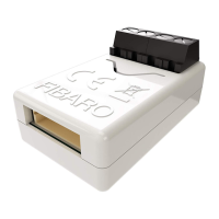
The FIBARO Smart Implant (SKU: FIBEFGBS-222) is a Z-Wave compatible device designed to enhance the functionality of wired sensors and other devices by integrating them into a Z-Wave network. It acts as a bridge, allowing traditional wired sensors to communicate with a Z-Wave controller, thereby expanding the capabilities of a smart home system. This device is a secure alarm sensor for Europe and requires connection to a mains power supply to operate.

Function Description

The Smart Implant enables various types of wired sensors to report their readings to a Z-Wave controller. It supports:

  • Binary sensors: These can be connected to the IN1/IN2 terminals to detect open/closed states, useful for alarm systems or simple on/off detection.
  • Analog sensors: The device can integrate 2-wire or 3-wire analog sensors, allowing for more nuanced data collection.
  • DS18B20 temperature sensors: Up to six DS18B20 sensors can be connected in parallel to the SP-SD terminals for precise temperature measurements.
  • DHT22 humidity and temperature sensors: A single DHT22 sensor can be connected to the TP-TD terminals for combined humidity and temperature readings.

Beyond just reporting sensor data, the Smart Implant can also control devices by opening or closing output contacts (OUT1 and OUT2), independently of the inputs. This allows for automation scenarios where sensor input triggers an action on a connected device. For example, it can be connected to a gate opener with an impulse input, where each impulse starts and stops the gate motor, alternating between opening and closing.

The device supports Z-Wave network Security Modes, including S0 with AES-128 encryption and S2 with PRNG-based encryption, ensuring secure communication within the network. It also functions as a Z-Wave signal repeater, extending the range and reliability of the Z-Wave network. A built-in temperature sensor provides additional environmental monitoring.

Usage Features

To integrate the Smart Implant into a Z-Wave network, it must first be in its factory default state. The inclusion process involves setting the main controller to "Security S2 Authenticated add mode," scanning the DSK QR code or inputting the 5-digit PIN code, and then powering the device. A blinking yellow LED indicates the adding process, and a successful addition is confirmed by the Z-Wave controller's message.

The Smart Implant offers extensive configuration parameters to adapt its function to specific user needs. These parameters allow users to:

  • Define input operating modes: Parameters 20 and 21 allow choosing the operating mode for IN1 and IN2, respectively, such as normally closed/open alarm input, monostable/bistable button, or analog input with/without internal pull-up.
  • Reverse input/output orientation: Parameters 24 and 25 enable reversing the operation of IN1/IN2 inputs and OUT1/OUT2 outputs without changing the physical wiring, useful for correcting incorrect wiring.
  • Configure sent scenes: Parameters 40 and 41 define which actions (e.g., single click, double click, hold) on IN1/IN2 result in sending scene IDs and attributes to the Z-Wave controller, enabling scene activation.
  • Set association group values: Parameters 47, 49, 52, and 54 define the values sent to association groups when IN1 or IN2 are activated or deactivated, allowing the Smart Implant to control other Z-Wave devices.
  • Adjust analog input reporting: Parameters 63 and 64 control the minimal change in analog input value required to send a new report and the periodical reporting period for analog inputs, respectively.
  • Configure temperature sensor reporting: Parameters 65 and 66 define the minimal change in internal temperature sensor value for new reports and the periodical reporting period. Similarly, parameters 67 and 68 do the same for external DS18B20 or DHT22 sensors.
  • Set input sensitivity and alarm cancellation delay: Parameters 150 and 151 adjust the inertia time for IN1 and IN2 in alarm modes to prevent signal disruptions. Parameters 152 and 153 define additional delays for cancelling alarms on IN1 and IN2.
  • Define output logic and auto-off: Parameters 154 and 155 define the logic of operation for OUT1 and OUT2 (normally open/closed when active). Parameters 156 and 157 set the time after which OUT1 and OUT2 will automatically deactivate.

The device also features a built-in Z-Wave network range tester. This allows users to check the communication range with the main controller, indicated by different LED pulsing patterns (green for direct communication, yellow for routed communication, violet for maximum distance, red for no connection).

Maintenance Features

For maintenance and troubleshooting, the Smart Implant provides several features:

  • Factory Reset: The device can be reset to factory default without a Z-Wave controller. This involves pressing and holding the button until it glows yellow, then quickly clicking it to confirm. This procedure should only be used when the primary controller is inoperable.
  • Exclusion: To remove the device from a Z-Wave network, the main controller is set to "remove mode," and the button on the device (or a switch connected to IN1 or IN2) is triple-clicked. A blinking yellow LED indicates the removal process, confirmed by the controller's message.
  • Visual Indications: The built-in LED provides visual feedback on the device's status:
    • Green: Device added to a Z-Wave network (without Security S2 Authenticated).
    • Magenta: Device added to a Z-Wave network (with Security S2 Authenticated).
    • Red: Device not added to a Z-Wave network.
    • Blinking cyan: Update in progress.
    • Green/Magenta (solid): Update successful.
    • Red (solid): Update not successful.
  • Menu System: The device has a menu accessible by pressing and holding the button, allowing for actions like range testing (magenta glow) and factory reset (yellow glow).
  • Antenna Arrangement Tips: To ensure optimal signal reception, the antenna should be located as far as possible from metal elements, not cut or shortened, and not stick out of the wall switch box.

The Smart Implant is designed for continuous operation as it is powered by a DC power supply unit, meaning it is always awake and does not have a deep sleep state like battery-operated devices. This ensures consistent communication and responsiveness within the Z-Wave network.

FIBARO Smart Implant Specifications

General IconGeneral
Power Supply9-30V DC ±10%
Radio ProtocolZ-Wave
Maximum Current at Outputs150mA
Maximum Voltage at Outputs30V DC / 20V AC
Radio Frequency868.4 or 869.8 MHz EU; 908.4 or 916.0 MHz US; 921.4 or 919.8 MHz ANZ; 869.0 MHz RU
RangeUp to 50m outdoors; Up to 40m indoors (depending on terrain and building structure)
Inputs2x Digital/Analog
Outputs2x potential-free outputs
CertificationRoHS 2011/65/EU, RED 2014/53/EU
Measuring Range of the Temperature Sensor-55°C to 126°C (-67°F to 259°F)