EasyManua.ls Logo

Field Controls CAS-4 - User Manual

Field Controls CAS-4
12 pages
Print Icon
To Next Page IconTo Next Page
Loading...
www.fieldcontrols.com
Please retain these instructions after installation.
This device MUST be installed by a qualified agency in accordance with the manufacturer's installation instructions. The definition of
a qualified agency is: any individual, firm, corporation or company which either in person or through a representative is engaged
in, and is responsible for, the installation and operation of HVAC appliances, who is experienced in such work, familiar with all the
precautions required, and has complied with all the requirements of the authority having jurisdiction.
READ THESE INSTRUCTIONS CAREFULLY AND COMPLETELY BEFORE PROCEEDING WITH THE INSTALLATION.
Installation Date:
Installed By: Phone:
COMBUSTION AIR SYSTEM
MODEL: CAS-4
This product is designed for use with any natural gas or LP burning furnace, water heater, or boiler with a
24 VAC control system. It may be used with a millivolt powered system with additional hardware. It may
also be used with more than one appliance. The CAS unit mechanically draws air into a structure and
disperses it near the combustion air intake of an appliance. If an optional Vacuum Relief Valve (VRV) is
used, the incoming air is tempered before entering the structures airspace. Refer to Diagrams A and B for
guidance in setting up the CAS system based on the size and length of the connecting ductwork and the
input rating of the appliance.
ITEMS INCLUDED IN KIT:
1- Motorized Blower
1- 4" galvanized intake air Vent Hood
2- Mounting brackets to secure the CAS to a wall
2- Wire/conduit connectors
1- 4" x 6" Pipe Increaser Fitting
1- 6" Orifice Ring
1- Instruction Sheet
1- High/Low Motor Speed Switch
Question and Answer IconNeed help?

Do you have a question about the Field Controls CAS-4 and is the answer not in the manual?

Overview

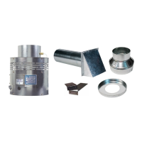
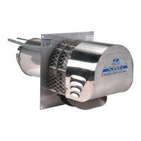
The Field Controls CAS-4 Combustion Air System is a motorized blower designed to provide combustion air for natural gas or LP burning furnaces, water heaters, or boilers with a 24 VAC control system. It can also be used with millivolt-powered systems with additional hardware and is capable of serving multiple appliances. The unit mechanically draws outside air into a structure and disperses it near the combustion air intake of the appliance. An optional Vacuum Relief Valve (VRV) can be used to temper the incoming air before it enters the living space.

Function Description:

The CAS-4 operates in conjunction with the appliance's control system. When the thermostat or aquastat calls for heat, it energizes a relay that activates the CAS unit. Once the CAS fan reaches operating speed, an internal air pressure switch closes, completing the circuit and allowing the burner to fire. In power-vented systems, the venter and CAS activate simultaneously. After the heating requirement is satisfied, the thermostat circuit opens, deactivating both the burner and the CAS unit. For power-vented systems with a post-purge device, the power venter and CAS will continue to operate for a period to purge remaining flue gases from the vent system.

Important Technical Specifications:

  • Compatibility: Designed for natural gas or LP burning furnaces, water heaters, or boilers with 24 VAC control systems. Adaptable for millivolt-powered systems with additional hardware.
  • Airflow Characteristics: Supports 4" and 6" diameter sheet metal duct pipe and includes an orifice ring for airflow adjustment.
  • Motor Speed Control: Equipped with a High/Low motor speed control switch to adjust airflow based on application requirements.
  • Electrical Requirements: Operates on 120VAC, 60HZ. The wiring should be protected by an over-current circuit device rated at 15 amperes.
  • Included Components:
    • 1 Motorized Blower
    • 1 4" galvanized intake air Vent Hood
    • 2 Mounting brackets
    • 2 Wire/conduit connectors
    • 1 4" x 6" Pipe Increaser Fitting
    • 1 6" Orifice Ring
    • 1 Instruction Sheet
    • 1 High/Low Motor Speed Switch

Usage Features:

  • Sizing and Setup: The manual provides diagrams (Diagrams A and B) and a table (Table 1) to determine the maximum equivalent length and size of duct pipe based on the appliance's total input firing rate (BTU/hr) and the desired motor speed (High or Low). This ensures proper airflow for the appliance.
  • Ductwork Calculation: Users calculate the total equivalent length of duct pipe, including elbows and fittings, to connect the CAS unit to the vent hood.
  • VRV Integration (Optional): The Vacuum Relief Valve (VRV) can be installed directly on the air inlet of the CAS unit (if using 6" duct) or near the intake air hood. Its balance weight can be adjusted to reduce the amount of air drawn in or to mix room air with outside air for tempering in cold climates. The VRV should be oriented so that the axis of the swinging gate is horizontal.
  • Placement: The CAS unit should be located on a flat horizontal surface within the same space as the appliance and within 3 feet of the combustion air intake. Mounting brackets are provided for securing the unit to a solid structure, though they are not required if the unit is stable.
  • Intake Air Hood Location: The 4" galvanized vent hood should be placed on an outside wall, maintaining minimum clearances to other intake and exhaust vents according to the National Fuel Gas Code, ANSI Z223.1, manufacturer's recommendations, and local codes. It should be at least 10 feet from a power-vented exhaust outlet on the same wall and a minimum of 1 foot above grade or snowlines.
  • Duct Installation: Duct pipe (4" or 6" diameter) connects the CAS unit to the vent hood. A 4" x 6" Pipe Increaser Fitting is used if connecting 4" pipe to the CAS unit (or VRV). Ductwork should be supported with mounting straps from floor joists, walls, or other solid structures. A minimum of 12 feet of pipe is recommended to help temper incoming outside air.
  • Wiring: The unit must be grounded and wired according to the National Electric Code and local codes. Wiring should be protected by a 15-ampere over-current circuit device. Internal wiring connections and external wiring diagrams for various applications (e.g., chimney vent single 24V furnace, power vent single 24V furnace, chimney vent 24V furnace and 30mV water heater, chimney vent 24V boiler, power vent single 24V boiler, chimney vent two 24V gas appliances, one power venter two 24V gas appliances) are provided.

Maintenance Features:

  • Annual Inspection: Inspect the system annually to ensure proper operation: verify the fan activates when heat is called for and deactivates when the call is satisfied.
  • Power Disconnect Test: Disconnect power to the CAS unit and repeat the annual inspection test. The unit should not run, and the appliance should not fire.
  • Duct Pipe Inspection: Inspect the duct pipe for cracks and ensure its secure connection to the CAS unit, VRV (if installed), and vent hood.
  • Obstruction Clearance: Clear any obstructions from the inlet of the vent hood and the outlet of the CAS unit.
  • Fan Blade Cleaning: Periodically clean the fan blade chamber. This involves disconnecting power, removing the duct pipe, removing the top pan, cleaning the fan housing area, and then reassembling.
  • Replacement Parts: The manual lists available replacement parts:
    • Motorized Fan (Field Part Number: 46274100)
    • Air Pressure Switch (Field Part Number: 46273100)
    • 24 VAC Relay for CAS-4 (Field Part Number: 46161400)
    • Replacement parts require power disconnection and unit disassembly. Users are advised to note the positions of components before removal. Technical support is available for assistance.

Field Controls CAS-4 Specifications

General IconGeneral
BrandField Controls
ModelCAS-4
CategoryFan
LanguageEnglish

Related product manuals