3
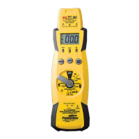
1. DATA HOLD freezes display with the touch of a button,
indicator in LCD turns on. A second touch resets.
2. MAX HOLD remembers the largest number displayed,
indicator in LCD turns on. Second touch resets.
3. Phase rotation feature identifies phase relationship of
three-phase power. "L1L2L3" indentifies which connec-
tions have been made. "FOR" indicates L1, L2, and L3 are
connected in order. "REV" indicates you must switch any
two leads.
4. Indicator lights and beeper sounds intermittently when
connected to voltages greater than 30V.
5. Low battery indicator.
6. Single rotary switch for function and range selection:
V
Volts DC
V Volts AC
Hz Frequency
L1L2L3 Phase rotation
µF Micro Farads (capacitance)
Ω Ohms
Continuity beeper
or diode test
7. Most accessories use 200mV range. For readings
over 200, use the 2000mV range. Use 200mV or
2000mV range for the AC current clamp accessory.
8. For volts, ohms, or measurements using any accessory,
use this jack and COM.
9. Always plug one test lead in this jack.
10. For testing current going THROUGH the meter (i. e. NOT
using an amp clamp accessory) use one of these jacks (and
COM) and one of these switch positions.
WARNING!
UNDER NO CIRCUMSTANCES EXCEED THESE RATINGS:
850VAC/1200VDC on voltage ranges (500VDC/350VAC on 200mV
range); 500V (AC or DC) on ohms, diode/continuity, and frequency
ranges; 450V phase rotation range; 200mA/500V on mA jack; 20A/600V
on A jack. FULLY DISCHARGE CAPACITORS BEFORE TESTING!
DO NOT USE THE ACH 300A CLAMP HEAD ON UNINSULATED
CONDUCTORS ABOVE 600VAC. DISCONNECT THE METER FROM
THE CIRCUIT BEFORE TURNING ANY INDUCTOR OFF, INCLUD-
ING MOTORS, TRANSFORMERS, AND SOLENOIDS.