7M User’s Manual 8
2. CONNECTION
This chapter deals with the instructions for single-phase electrical energy meter 7M.24 connection. Both the use and
connection of the device includes handling with dangerous currents and voltages. Connection shall therefore be performed
ONLY by a qualied person using an appropriate equipment. Finder S.p.A. does not take any responsibility regarding the use
and connection. If any doubt occurs regarding connection and use in the system which device is intended for, please contact
a person who is responsible for such installations.
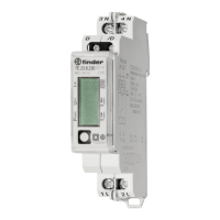
2.1 Mounting
Single-phase electrical energy meter 7M.24 is intended only for DIN-rail mounting. In the case of using the stranded wire, the
ferrule must be attached before the mounting. Ferrule contact length should be 12 mm.
2.2 Electrical connection
Wrong or incomplete connection of voltage or other terminals can cause non - operation or damage to the device.
• To prevent electrical shock and/or equipment damage, disconnect electrical power at the main fuse or circuit breaker
before installation or any servicing
• Make sure, that no voltage is present in the installation
• Prevent the disconnecting device from being switched on accidentally
• Connect the module according to electrical diagram
Security seal must be from plastic material
Meter is used for direct connection into the two-wire networks. Meter can be equipped with dierent modules.
Pictures below are showing equipped combinations.
Recommended installation:
1 Mounting to DIN rail according to DIN EN60715
2 Power contacts:
• Power contacts capacity: Flexible (Rigid) 1.5 mm
2
– 10* mm
2
(*Ferrule contact length should be 12 mm
Wire stripped to 14 mm.)
• Connection screws M3.5
• Max torque 0.8 Nm
3 Auxiliary terminals:
• Auxiliary terminals contact capacity: Flexible (Rigid) 0.05 mm
2
– 1 (2.5) mm
2
• Auxiliary terminals screws M3
• Max torque 0.6 Nm
WARNING
WARNING

 Loading...