Do you have a question about the Finest 705 Series and is the answer not in the manual?
Specifies the range for DC voltage measurements.
Defines the range and bandwidth for AC voltage measurements.
Details the accuracy for DC and AC voltage measurements.
Specifies the range for DC current measurements.
Defines the range for AC current measurements.
Specifies the range for resistance measurements.
Defines the range for conductance measurements.
Specifies the range for capacitance measurements.
Defines the range for frequency measurements.
Specifies the range for duty cycle measurements.
Details the voltage for diode testing.
Specifies the temperature measurement range.
Indicates the number of memory locations available.
Defines the threshold for continuity beeps.
Covers warnings and cautions for safe operation and potential hazards.
Lists and explains common electrical symbols used in the manual.
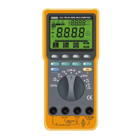
Identifies and describes the multimeter's controls and display indicators.
Instructions on how to power on the multimeter.
Details on using the rotary switch to select functions.
Description of the analog bar graph feature for visual indication.
Instructions for using the RANGE button for manual and auto-ranging.
How to record minimum, maximum, and average readings.
Capturing transient events with 1ms peak hold.
Setting the meter to relative mode for measurements.
Functionality for freezing and automatically holding readings.
Storing, recalling, and clearing measurement values.
Controls the LCD backlight.
Using keys to navigate and select on-screen menu options.
Configuring auto-power-off, backlight, and beep alerts.
Explains how to use menu keys for editing setup values.
General steps for performing measurements using the meter.
Introduction to voltage measurement ranges and functions.
Detailed operation for AC voltage measurements.
Measuring AC voltage in decibels (dBm or dB V).
Detailed operation for DC voltage measurements.
Measuring combined AC and DC voltage components.
Simultaneous display of AC and DC components.
Operating the meter for frequency measurements.
Measuring the ON or OFF time of signals as a percentage.
Measuring the duration of high or low signal states.
Instructions and tips for measuring resistance.
Using the continuity function to detect opens and shorts.
Measuring conductance as the inverse of resistance.
Procedures for measuring capacitance values.
Testing diodes and semiconductors by measuring voltage drop.
Using the meter with a thermocouple for temperature readings.
Guidelines for measuring AC and DC current.
Measuring true RMS AC current.
Measuring DC current.
Measuring combined AC and DC current.
Simultaneous display of AC and DC current components.
Alerts for incorrect input connections or fuse issues.
Switching between automatic and manual ranging modes.
Understanding the beeper signals for operation and errors.
Explanation of the automatic power saving feature.
Proper procedures for cleaning and storing the meter.
How the meter checks fuse integrity.
Steps for replacing the battery and fuses.
Guidance for resolving common operational issues.
Details on safety standards and voltage ratings.
List of certifications obtained by the meter.
Information on the meter's surge protection rating.
Dimensions, weight, and display characteristics.
Overview of key features like backlight and autoranging.
Accuracy tables for DC voltage measurements.
Accuracy tables for DC current measurements.
Accuracy tables for AC current measurements.
Accuracy tables for AC voltage measurements.
Accuracy for conductance measurements.
Accuracy for diode test function.
Accuracy tables for capacitance measurements.
Accuracy specifications for Frequency, Duty Cycle, and Pulse Width.
Accuracy for temperature measurements.
Specifications for dBm measurements.
Accuracy for 1ms PEAK hold measurements.
Typical burden voltage for current measurement ranges.
The Finest Model 705 & 707 Series True RMS Multimeters are advanced test and measurement devices designed for a wide range of electrical measurements. These multimeters are manufactured by Fine Instruments Corporation, a company based in Bucheon-shi, Kyunggi-do, Korea, specializing in test and measurement equipment.
The multimeters offer comprehensive measurement capabilities, including:
| Brand | Finest |
|---|---|
| Model | 705 Series |
| Category | Multimeter |
| Language | English |