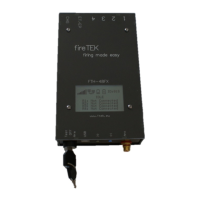
The FireTEK FTM-48Fx and FTM-48Sx are firing devices designed for pyrotechnic displays, offering a range of functionalities for both standalone and master/slave operations. This quick guide provides an overview of their features, usage, and maintenance.
Function Description
The FireTEK devices are primarily used for firing pyrotechnic events. They can operate in various modes, including InitMode, TestMode, Test, Armed, Play, and Pause, allowing for flexible control over firing sequences. The devices support both programmed events (PRG) and DMX events, catering to different types of pyrotechnic shows. They can function as standalone units or as part of a master/slave setup, enabling synchronized firing across multiple devices.
Important Technical Specifications
The devices feature a display that provides critical information, including:
- ID - Interface ID: A unique identifier for the device.
- I - INIT mode: Indicates the initialization mode.
- A - Stand alone mode: The device operates independently.
- M - Master mode: The device controls other slave units.
- S - Slave mode: The device is controlled by a master unit.
- Status (PRG): Shows if the device is programmed for pyro events or DMX events.
- Wireless field strength indicator (S - standard network, C - Custom Network): Displays the strength of the wireless signal.
- 2-wire connection status (connected/not connected): Indicates the status of the 2-wire connection.
- Rail 1-4 indicators: Provide visual feedback on the status of the firing rails.
Connectors:
- USB connector: For connecting to a computer or other USB devices.
- DMX output connector (optional): For DMX control of lighting or other effects.
- Buttons (Green & Blue): Used for various functions and navigation.
- 2-wire connectors (opt.): For establishing 2-wire communication between devices.
- Time code input (optional): For synchronizing with external time code sources.
- Charging port: For recharging the internal battery.
- External trigger/power connector: For external power supply or triggering events.
- Rail (1-4) connectors: For connecting igniters to the firing rails.
Power and Battery:
The devices are equipped with an internal battery, and an external battery indicator is present on the display. They can be powered on using a key switch.
Usage Features
Setting ID-number:
The ID number can only be set when the device is in the firing mode. If the device is programmed, the program must be deleted to change the ID number.
- Turn power on (Key switch to test position).
- When the device asks to set the ID number, press the blue button to increase the number and the green button to confirm it. For a fast increase of the ID, press and hold the blue button.
Field Testing:
Users can test connections and module status without the risk of accidental firing.
- Power on the module without pressing any button.
- Wait until TestMode appears on the screen.
- Check the module rail connections.
- If a script is present on the module, it will display which rails/igniters should be connected and not.
- Check the battery level.
- In TestMode, the buttons are disabled, preventing accidental firing.
- In TestMode, the module will reset automatically every minute.
Channel Connection Legend (E-match igniters continuity test legend):
- IDLE state:
- O - Not connected
- Ж - Bad connection
- ☐ - Good connection
- ■ - Very good connection
- V - Programmed but not connected
- ? - Connected but not programmed
- X - Lock out from fire
- ARMED / PLAY / PAUSE state:
- O - Not connected or fired
- ● - Connected and not fired
- X - Lock out from fire
Use of one device as Standalone (without remote):
Precondition: Module is programmed.
- For safety reasons, to use the module without a remote, you need to press and hold the green button while powering on the module until INIT appears on the screen.
- The module is now ready to use and will show the rail status on the screen.
- Short press the green button to go into TEST state.
- To arm the module, you will need to press and hold the green button until the module state changes to ARMED.
External trigger control:
- To be able to control the system via an external trigger, you will need to give an impulse on the external trigger connector, and the second battery will be displayed as ET.
- To go into test mode where you can test the external trigger without starting the script, in TEST state, every time the module receives an impulse on the external trigger, ET will become AT for a second.
- While the module is ARMED, press the green button. The module enters PLAY-state and fires according to the script.
- If the green button is pressed again, the module changes to PAUSE, and continues again firing after the green button is pressed again.
- If the blue button is pressed, the module disarms and enters INIT state.
B. Firing automatic using external trigger:
- In ARMED state, if the module detects an impulse on the external trigger, the module goes into PLAY state.
- In PLAY state, if the module detects a new impulse, it will pause the script and resume it on the next impulse.
- While the module is ARMED, press the blue button. The module goes into step by step mode or Seq by Seq mode, if the scripts contain sequences.
- In step by step mode, if the green button is pressed, the next channel based on script order will be fired. Channels programmed to be fired in the same time, will be fired in the same time. If the blue button is pressed, the next channel will be skipped.
- In Seq by Seq mode, if the green button is pressed, the next sequence is fired.
D. Firing step by step using External trigger:
When an impulse is detected on the external trigger, the next channel or sequence will be started.
Use of one device as Master (without remote):
Set the module as Master:
- On the module, which you are going to use as master, press the green button and keep it pressed while powering on until INIT appears on the screen.
- To set the module as Master, press and hold the blue button and short press the green button, release both. The module is now in POWER ON SLAVES state.
Connect all other modules to Master:
- Power on all other modules you have (master can work even without slaves).
- Wait until all slaves are shown on the master screen SLAVES:x
- Press the green button again. The master enters TEST mode.
Control the system:
In this mode, you can control the entire system (Master with all modules connected to it) via Master using: Panel buttons, Other firing system via External trigger, External player or other controller via Time code, Computer software via USB, Android application via USB or Bluetooth, Time with GPS Time.
Maintenance Features
The manual does not explicitly detail maintenance features beyond the field testing and battery level checks. However, the presence of a charging port indicates that battery maintenance is a key aspect of device upkeep. Regular checks of connections and module status during field testing can help identify potential issues before a show. The ability to reset the module in TestMode automatically every minute suggests a built-in mechanism for maintaining operational readiness during testing.