29
The format of the data is 4800, N, 8, 1 meaning 4800 baud, no parity, and 1 stop bit.
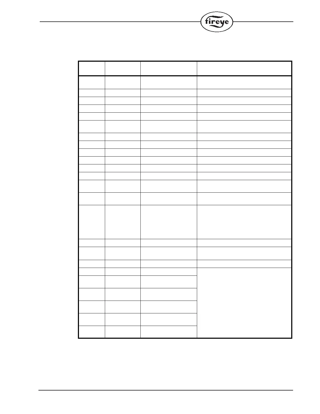
Below is a table of currently available messages provided by the MicroM programmers, followed by
a description where necessary.
Messages 00, 05, 08, 10, 15, 21 and 26 are unique in that a limited number of successive registers
can be combined with these requests. For example, a request to message 00 can contain up to 6 data
words. The response to this would contain STATUS, MSGN, GSTAT, TIMER, FLAME and LOG-
STAT. If the requested data word count (DAT) were to be 2 then the response would contain STA-
TUS and MSGN only. Message 15, last 6 lockouts, can return data ranging from 1 to 6, with 1
referring to the most recent lockout.
MESSAGE
ADDRESS
WORDS
REQUESTED
RESPONSE VALUE
00 1-6 STATUS 83 (053H) = RUN;
202 (0CAH) = LOCKOUT
01 1 MSGN Current message being displayed (see Table 3)
02 1 GSTAT Defines Timer Type
03 1 TIMER Time, Flame, Address
04 1 FLAME Flame Signal
05 1-3 LOGSTAT Current logic module, PURGE, PTFI, AUTO (See
Table 1)
06 1 INPUTS Input limits state
07 1 OUTPUTS Output relays state
08 2, 4 or 8 SYSMINS System on minutes
10 2 or 4 BNRMINS Burner on minutes
12 2 CYCLES Completed Burner Cycles
14 1 LOCKOUT COUNT Stored Lockout Count
15 1-6 LOCKOUT HISTORY Last 6 Lockouts, first word is most current lock-
out
21 1-2 DEVTYP Programmer device type, 5=EP, 6=EPD,
7=MicroM
22 1 AMPTYP Amplifier Type;
MECD=080H;
MEUV=090H;
MEIR=0A0H;
MERT=0B0H;
MEUVS=0C0H
23 1 PROGTYP Programmer Type (See Table 2)
24 2 FLAME SIGNAL
AVERAGES
PTFI and Auto Flame Signal Averages
26 1-9 Combined Status See Description Below
35 6 Most Recent Lockout Data
Returns complete lockout description of stored
lockout history. Includes lockout message,
lockout module, @ burner hours, and @ burner
cycles
41 6 2nd Most Recent Lockout
Data
47 6 3rd Most Recent Lockout
Data
53 6 4th Most Recent Lockout
Data
59 6 5th Most Recent Lockout
Data
65 6 6th Most Recent Lockout
Data
 Loading...