ROBO I
NTERFACE
O
PERATING
I
NSTRUCTIONS
GB+USA
ROBO I
NTERFACE
O
PERATING
I
NSTRUCTIONS
GB+USA
12
13
Assignment of the keys on the IR hand transmitter:
The motor outputs M1–M3 of the interface can be turned on and turned off with the corresponding keys on
the transmitter. For M1–M3, the speed of the motor can also be switched to fast and slow.
The motor output M4 is activated with the keys 1))) and 2))), but these keys are normally used to switch
between receiver 1 and receiver 2. The speed of M4 cannot be changed with the hand transmitter.
Twenty-six Pin Strip (13)
Here all available inputs and outputs are provided again so that you, if desired, can connect a model through
a ribbon cable and a single 26-pin plug with the interface (plug and ribbon cable are required additionally).
Expansion Plug for ROBO I/O Extension (15)
Using the ROBO I/O extension (item No. 93294 required additionally), the number of the inputs and outputs
can be expanded. It has four additional motor outputs with speed control, eight digital inputs and one analog
resistance input for 0–5.5kΩ.
Expansion Plug for ROBO RF Data Link (19)
The ROBO RF data link is an optional radio interface for the ROBO interface (item No. 93295 required
additionally). With this, a cable connection between the PC and the interface is no longer needed! The RF data
link is connected to the USB interface of the PC. Frequency 2.4 GHz, range about 10 m.
1
3
5
7
9
11
13
15
17
19
21
23
25
2
4
6
8
10
12
14
16
18
20
22
24
26
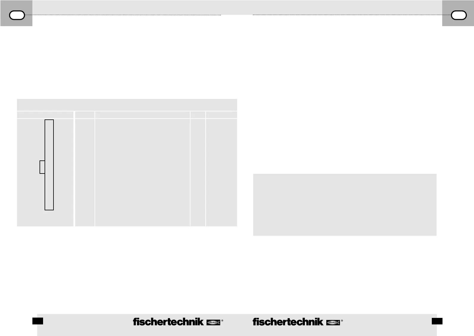
Supply voltage 9 V + for sensor supply
Ground wire for analog connections, gap sensor,
fast meter input. Do not use as antipole for
the power output O1 to O8.
AX
AY
A1
A2
Gap sensor D1
Gap sensor D2
Fast meter input
Ground wire as antipole for the power output
O1 to O8.
11
12
13
14
15
16
17
18
19
20
21
22
23
24
25
26
I1
I2
I3
I4
I5
I6
I7
I8
O1
O2
O3
O4
O5
O6
O7
O8
1
2
3
4
5
6
7
8
9
10
Programing the Interface
n The standard programming software for the ROBO interface is the graphic programming language, ROBO Pro.
The interface works in the following operating modes.
Online Mode
The interface is continually connected to the PC (USB, serial cable or RF data link). The program runs on the
PC and the monitor serves as the user interface.
”Intelligent Interface Mode”
By pressing and holding the push button (5) down for at least three seconds, the interface switches to the
”intelligent interface mode.” You recognize this operating mode by the fast blinking of the serial interface LED
(7). In this mode, only the serial interface with the parameters 9600,n,8,1 is active. The ROBO interface
behaves then like an intelligent interface (item No. 30402). Thus, it can be controlled with the software, LLWin
3.0, in the online mode. Downloading LLWin programs is not possible! Press the key (5) quickly, and you return
to the automatic interface selection of the ROBO interface.
The Download Mode
In this operating mode, a program is loaded onto the interface and runs independent of the PC. Two different
programs can be loaded into the FLASH memory. These are still retained even after the power supply is turned
off. It is also possible to load a program into the RAM. This program is deleted as soon as the power supply
is interrupted or a program is started, which is in the FLASH memory.
Note!
The storage of programs in the RAM goes significantly faster than storing it in the FLASH because the
FLASH must be erased first and this takes some seconds. In the test stage, the program can thus only be
loaded into the RAM. Ideally, you first store the final version of a program in the FLASH. This also extends
the service life of the FLASH, which is ”limited” to about 100,000 writing cycles.
The instructions for use of the ROBO Pro software describe how to load a program into the particular memory
of the interface.
Use push button (4) to select, start and stop programs, which are stored. To select a program, press and hold
push button (4) down. If a program was stored in Prog1, then after about one second, the ”Prog1” LED lights
up. If you hold the push down for about one more second, then it switches to ”Prog2,” if a program is stored
there. After one more second, the program 3 (both LEDs are illuminated) would be selected in the RAM, if
anything is stored there. After one more second, then both LEDs are turned off. Then no program has been
selected.
Pin Assignment
Plug Assignment Pin Pin Assignment Pin Pin Assignment
 Loading...