6
(Continue Page 10)
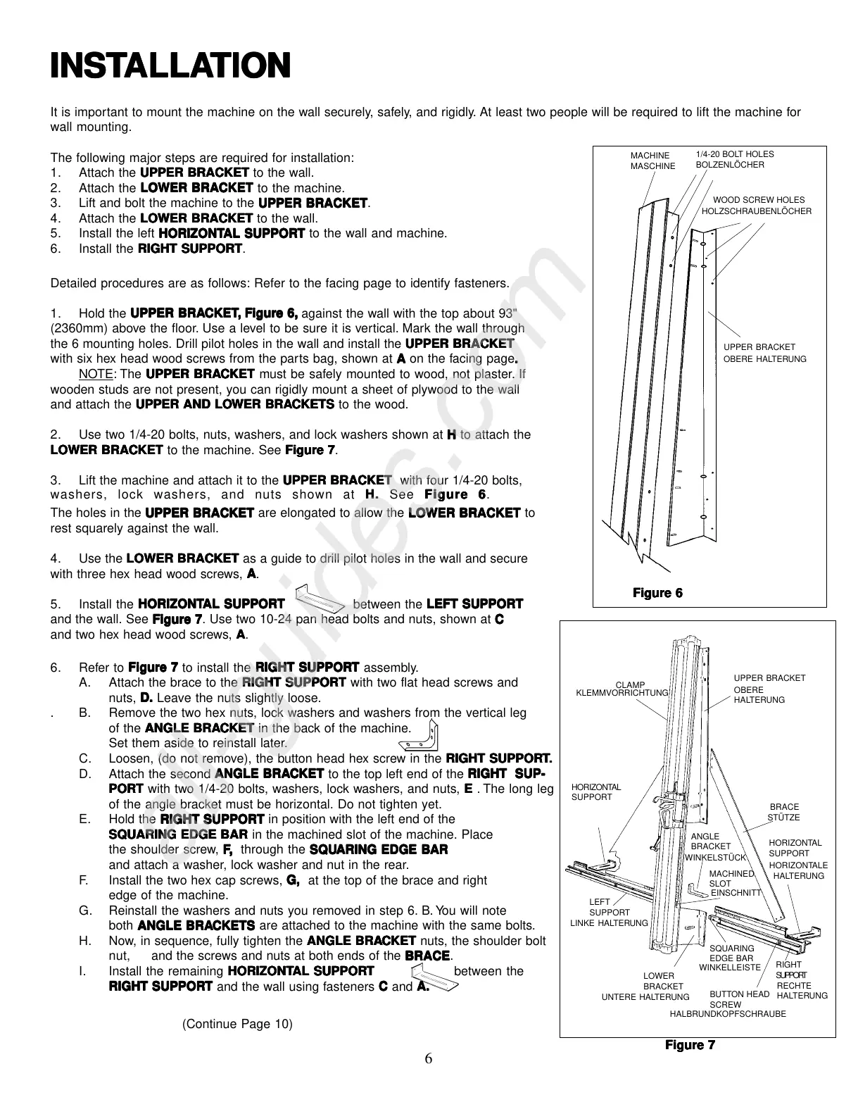
Detailed procedures are as follows: Refer to the facing page to identify fasteners.
1. Hold the
UPPER BRAUPPER BRA
UPPER BRAUPPER BRA
UPPER BRA
CKETCKET
CKETCKET
CKET
,,
,,
,
F F
F F
F
igureigure
igureigure
igure
6, 6,
6, 6,
6,
against the wall with the top about 93"
(2360mm) above the floor. Use a level to be sure it is vertical. Mark the wall through
the 6 mounting holes. Drill pilot holes in the wall and install the
UPPER BRACKETUPPER BRACKET
UPPER BRACKETUPPER BRACKET
UPPER BRACKET
with six hex head wood screws from the parts bag, shown at
A A
A A
A on the
facing page
..
..
.
NOTE: The
UPPER BRAUPPER BRA
UPPER BRAUPPER BRA
UPPER BRA
CKETCKET
CKETCKET
CKET must be safely mounted to wood, not plaster. If
wooden studs are not present, you can rigidly mount a sheet of plywood to the wall
and attach the
UPPER AND LOUPPER AND LO
UPPER AND LOUPPER AND LO
UPPER AND LO
WER BRAWER BRA
WER BRAWER BRA
WER BRA
CKETSCKETS
CKETSCKETS
CKETS to the wood.
2. Use two 1/4-20 bolts, nuts, washers, and lock washers shown at
HH
HH
H to attach the
LOWER BRACKET LOWER BRACKET
LOWER BRACKET LOWER BRACKET
LOWER BRACKET to the machine. See
Figure 7Figure 7
Figure 7Figure 7
Figure 7.
3. Lift the machine and attach it to the
UPPER BRACKET UPPER BRACKET
UPPER BRACKET UPPER BRACKET
UPPER BRACKET with four 1/4-20 bolts,
The holes in the
UPPER BRACKETUPPER BRACKET
UPPER BRACKETUPPER BRACKET
UPPER BRACKET are elongated to allow the
LOWER BRACKETLOWER BRACKET
LOWER BRACKETLOWER BRACKET
LOWER BRACKET to
rest squarely against the wall.
4. Use the
LOWER BRACKETLOWER BRACKET
LOWER BRACKETLOWER BRACKET
LOWER BRACKET as a guide to drill pilot holes in the wall and secure
with three hex head wood screws,
A A
A A
A.
5. Install the
HORIZONTHORIZONT
HORIZONTHORIZONT
HORIZONT
AL SUPPORAL SUPPOR
AL SUPPORAL SUPPOR
AL SUPPOR
TT
TT
T between the
LEFT SUPPORTLEFT SUPPORT
LEFT SUPPORTLEFT SUPPORT
LEFT SUPPORT
and the wall. See
Figure 7Figure 7
Figure 7Figure 7
Figure 7. Use two 10-24 pan head bolts and nuts, shown at
C C
C C
C
and two hex head wood screws,
AA
AA
A.
washers, lock washers, and nuts shown at
HH
HH
H
. .
. .
. See
Figure 6Figure 6
Figure 6Figure 6
Figure 6.
LEFT
SUPPORT
6. Refer to
Figure 7Figure 7
Figure 7Figure 7
Figure 7 to install the
RIGHT SUPPORRIGHT SUPPOR
RIGHT SUPPORRIGHT SUPPOR
RIGHT SUPPOR
TT
TT
T assembly.
A. Attach the brace to the
RIGHT SUPPORTRIGHT SUPPORT
RIGHT SUPPORTRIGHT SUPPORT
RIGHT SUPPORT with two flat head screws and
nuts,
D.D.
D.D.
D. Leave the nuts slightly loose.
. B. Remove the two hex nuts, lock washers and washers from the vertical leg
of the
ANGLE BRAANGLE BRA
ANGLE BRAANGLE BRA
ANGLE BRA
CKETCKET
CKETCKET
CKET in the back of the machine.
Set them aside to reinstall later.
C. Loosen, (do not remove), the button head hex screw in the
RIGHT SUPPORRIGHT SUPPOR
RIGHT SUPPORRIGHT SUPPOR
RIGHT SUPPOR
TT
TT
T
..
..
.
D. Attach the
second
ANGLE BRAANGLE BRA
ANGLE BRAANGLE BRA
ANGLE BRA
CKETCKET
CKETCKET
CKET to the top left end of the
RIGHT SUP-RIGHT SUP-
RIGHT SUP-RIGHT SUP-
RIGHT SUP-
PORPOR
PORPOR
POR
TT
TT
T with two 1/4-20 bolts, washers, lock washers, and nuts,
EE
EE
E . The long leg
of the angle bracket must be horizontal. Do not tighten yet.
E. Hold the
RIGHT SUPPORTRIGHT SUPPORT
RIGHT SUPPORTRIGHT SUPPORT
RIGHT SUPPORT in position with the left end of the
SQUARING EDGE BARSQUARING EDGE BAR
SQUARING EDGE BARSQUARING EDGE BAR
SQUARING EDGE BAR in the machined slot of the machine. Place
the shoulder screw,
FF
FF
F
,,
,,
,
through the
SQSQ
SQSQ
SQ
UU
UU
U
ARING EDGE BARING EDGE B
ARING EDGE BARING EDGE B
ARING EDGE B
ARAR
ARAR
AR
and attach a washer, lock washer and nut in the rear.
F. Install the two hex cap screws,
G, G,
G, G,
G, at the top of the brace and right
edge of the machine.
G. Reinstall the washers and nuts you removed in step 6. B. You will note
both
ANGLE BRAANGLE BRA
ANGLE BRAANGLE BRA
ANGLE BRA
CKETSCKETS
CKETSCKETS
CKETS are attached to the machine with the same bolts.
H. Now, in sequence, fully tighten the
ANGLE BRAANGLE BRA
ANGLE BRAANGLE BRA
ANGLE BRA
CKETCKET
CKETCKET
CKET nuts, the shoulder bolt
nut, and the screws and nuts at both ends of the
BRACEBRACE
BRACEBRACE
BRACE.
I. Install the remaining
HORIZONT HORIZONT
HORIZONT HORIZONT
HORIZONT
AL SUPPORAL SUPPOR
AL SUPPORAL SUPPOR
AL SUPPOR
TT
TT
T between the
RIGHT SUPPORRIGHT SUPPOR
RIGHT SUPPORRIGHT SUPPOR
RIGHT SUPPOR
TT
TT
T and the wall using fasteners
CC
CC
C and
A.A.
A.A.
A.
Figure 6Figure 6
Figure 6Figure 6
Figure 6
INSTINST
INSTINST
INST
ALLAALLA
ALLAALLA
ALLA
TIONTION
TIONTION
TION
It is important to mount the machine on the wall securely, safely, and rigidly. At least two people will be required to lift the machine for
wall mounting.
The following major steps are required for installation:
1. Attach the
UPPER BRACKETUPPER BRACKET
UPPER BRACKETUPPER BRACKET
UPPER BRACKET to the wall.
2. Attach the
LOWER BRACKET LOWER BRACKET
LOWER BRACKET LOWER BRACKET
LOWER BRACKET to the machine.
3. Lift and bolt the machine to the
UPPER BRACKETUPPER BRACKET
UPPER BRACKETUPPER BRACKET
UPPER BRACKET.
4. Attach the
LOWER BRACKET LOWER BRACKET
LOWER BRACKET LOWER BRACKET
LOWER BRACKET to the wall.
5. Install the left
HORIZONT HORIZONT
HORIZONT HORIZONT
HORIZONT
AL SUPPORAL SUPPOR
AL SUPPORAL SUPPOR
AL SUPPOR
T T
T T
T to the wall and machine.
6. Install the
RIGHT SUPPORTRIGHT SUPPORT
RIGHT SUPPORTRIGHT SUPPORT
RIGHT SUPPORT.
SQUARING
EDGE BAR
MACHINE
1/4-20 BOLT HOLES
WOOD SCREW HOLES
MASCHINE
BOLZENLÖCHER
HOLZSCHRAUBENLÖCHER
UPPER BRACKET
OBERE HALTERUNG
CLAMP
UPPER BRACKET
BRACE
HORIZONTAL
SUPPORT
ANGLE
BRACKET
HORIZONTAL
SUPPORT
Figure 7Figure 7
Figure 7Figure 7
Figure 7
RIGHT
SUPPORT
KLEMMVORRICHTUNG
OBERE
HALTERUNG
HORIZONTALE
HALTERUNG
LINKE HALTERUNG
WINKELSTÜCK
EINSCHNITT
WINKELLEISTE
LOWER
BRACKET
UNTERE HALTERUNG
HALBRUNDKOPFSCHRAUBE
BUTTON HEAD
SCREW
RECHTE
HALTERUNG
STÜTZE
MACHINED
SLOT
 Loading...