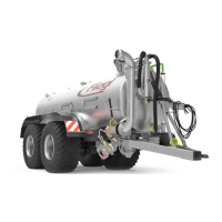
5.2 Layout of the machine
The following figure provides an overview of the most important components and assemblies and shows where they are
installed on the machine:
Fig. 1: Overview
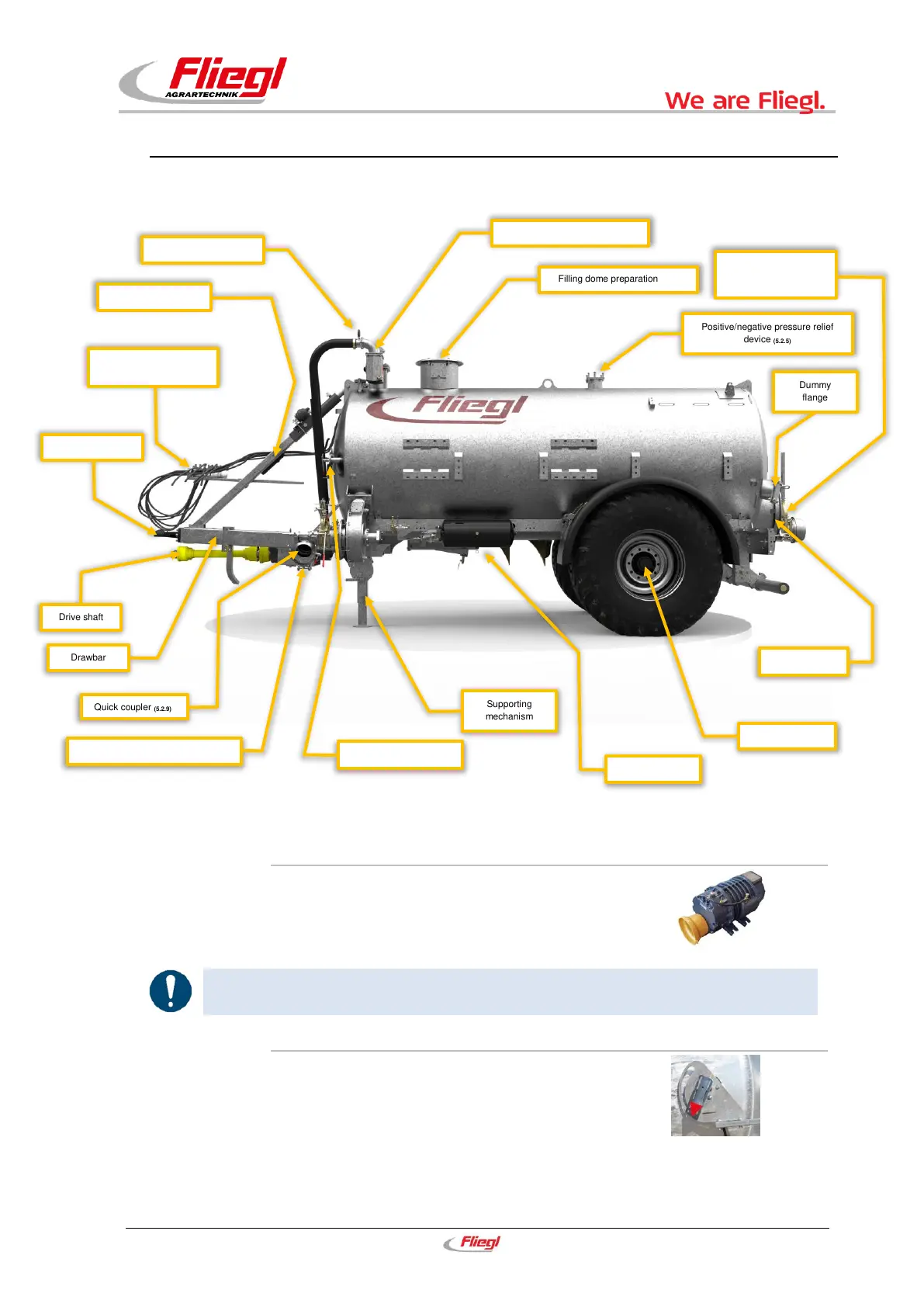
5.2.1 Heat-resistant compressor (standard)
The slurry is sucked into the tanker due to the negative pressure created by the
compressor. The slurry is discharged by means of the positive pressure, which is
also generated by the compressor. (Switching via compressor changeover)
The maximum operating pressure of 0.5 bar must not be exceeded.
5.2.2 Fill level indicator (standard)
The fill level indicator primarily serves as orientation during filling and assists in
the discharge process.
The fill level indicator (needle) is a prerequisite for a tank counter,
which is connected to the fill level indicator on specific axle assemblies with ALB
regulators.
Fig. 3: Fill level indicator
Positive/negative pressure relief
device
(5.2.5)
Filling dome preparation
(5.2.6)
Siphon & additional siphon
(5.2.7)
Hose holder & supply
connections
Heat-resistant compressor
(5.2.1)
Fill level indicator
(5.2.2)
Hydraulic gate valve
(5.2.4)
 Loading...