INSTALLATION
Insert the larger plug into the jack marked “headphone” or “phone”.
• Insert the smaller plug into the jack marked “microphone” or “mic”.
• Set the stereo/mono switch on the cable splitter box to the “M” position. If
connecting to a stereo intercom, set the switch to the “S” position.
• Adjust headband slider and mic boom for proper t and comfort.
• Place the microphone no more than 1/8” from lips, at the corner of the mouth.
This is critical to the performance of the noise canceling electret microphone.
• One volume control is located on the dome with the mic boom, to adjust the level
of audio.
If the aircraft does not have a built-in push-to-talk (PTT) switch, a portable PTT switch
must be installed in order to use the radio. The master gain control located in the
aircraft radio should be optimized by an avionics technician whenever adding a new
model microphone to the system.
HEADSET ADJUSTMENTS
Adjustable
headband
Adjustable
boom
Volume control
Mic Placement
Place mic no more than 1/8”
from lips. Placement of mic is
critical for proper operation.
WARNING
If the microphone is positioned incorrectly, you may
experience a reduction or interruption in the audio
and or deterioration in clarity of intercom and radio.
HEADSET FEATURES
• Passive noise reduction by 24db
• Stereo/mono switchable
• Noise-cancelling electret microphone
• Adjustable headband
• Flexible mic boom with slide adjustment for accurate mic positioning
SPECIFICATIONS
Technical Spec
• Weight ...................................... 17.1 oz Ave. (w/o Comm Cable)
• Noise Reduction Rating ............................................... 24db
Microphone
• DC Bias Supply .............................8 to 16 volts, not polarity sensitive
• Source Resistance .........................................220 to 2200 ohms
MIL SPEC
• Humidity & Temperature per MIL-STD 810F and 810G
• Chemical Exposure per MIL-STD 810F and 810G
SAE
• Salt Spray per J1455, Sec. 4.3
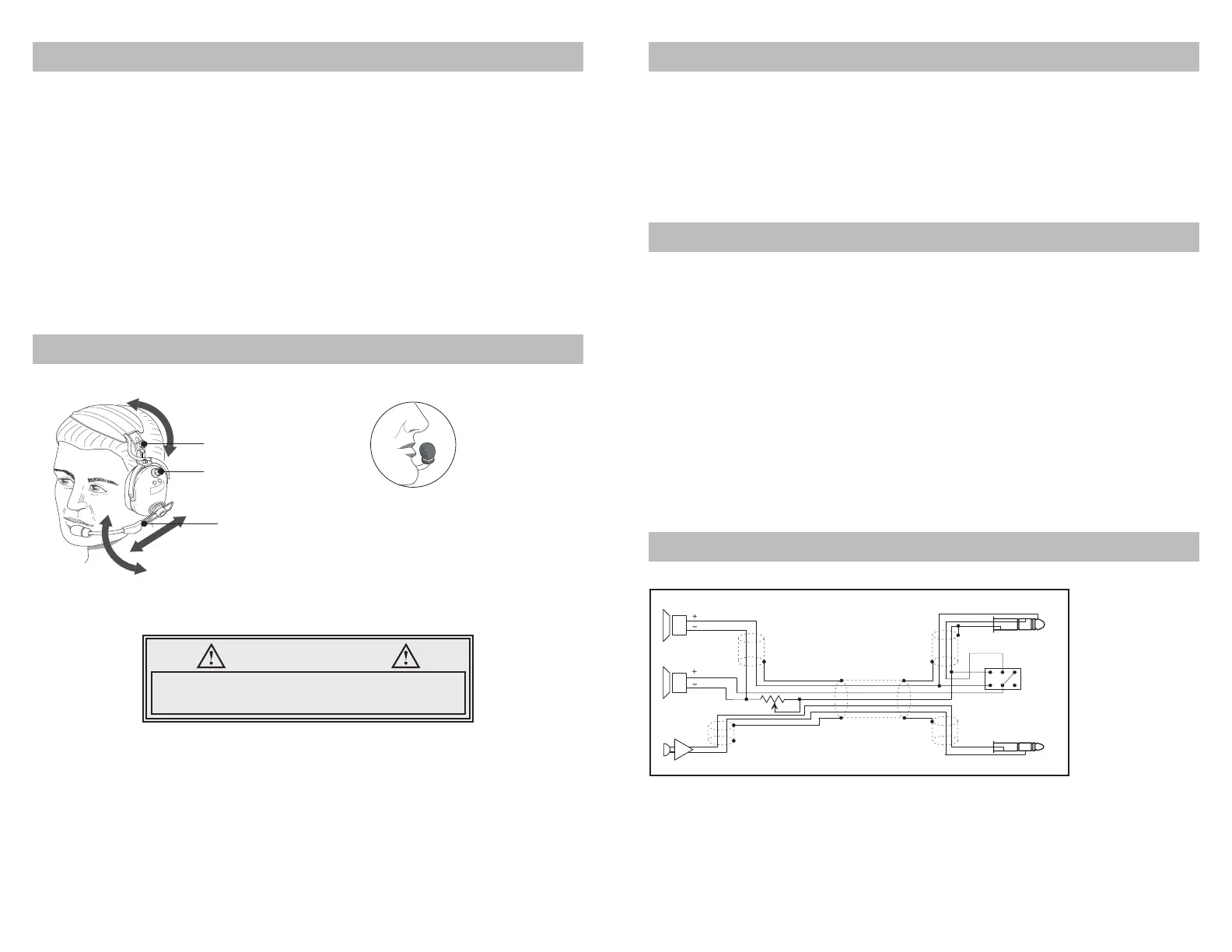
WIRING DIAGRAM
Caution:
Bias voltage supplied to the microphone must come from voltage and resistance
ranges specified above. Voltages supplied in excess of those stated in the
specifications can cause microphone failure and void warranty. The mic audio signal
is present between the ring and barrel of the mic plug; tip is reserved for transmit
keyline.
Right
Left
Speakers
Mic.
6.3 mm Plug
5.2 mm Plug
M
S
 Loading...