38 Rev. 03
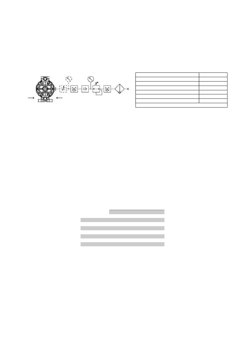
PNEUMATIC CONNECTION
WARNING: the pneumatic supply of “PHOENIX” series pumps must be carried out with oil-free, filtered, dry and
unlubricated air Avoid pressure drops by using pipes and adjusting and controlling elements having characteristics
suitable for the pump in case of installation in atex zone, the compressor must suck air from outside the area classified
as atex or use inert gas.
Minimum pressure supply 2 bar Maximum pressure supply 7 bar
1 – pressure regulator with gauge
2 - shut-off valve
3 – way valve
4 – flow regulator
INSTALLATION AND USE INSTRUCTIONS
TRANSPORT
• cover the hydraulic connections
• lift the hydraulic plastic parts without mechanical stress
• for transport on irregular roads, cushion the bumps with suitable support plane
• blows and impacts may damage parts that are important for the machine operation and safety
STORAGE
• In case you need to get away for a period of time the pumps before installation, store in original boxes. The boxes should be
stored off the ground, in a closed, clean and dry.
• in the event that the packaging has not received any is intact, it will be necessary to free the pump from it-Checking the integrity
and restore a new packaging
• The storage place should be closed environment with a temperature not lower than -5 ° C, not more than 40 ° C
and with a moisture content not exceeding the value of 80%; any packaging must not be subjected to shocks, vibrations and loads
above you
INSTALLATION
• it is essential for the pump self-priming operation that the hydraulic system is leak-proof
• clean the system before connecting the pump
• the pump must not contain foreign bodies and all the seals on the hydraulic connections must be removed
• before starting the pump check the tightness of the screws of the pump bodies and manifolds according to the following
schedule:
MODEL
PUMP CASING MANIFOLD
4-5 Nm 3-4 Nm
7-8 Nm 4-5 Nm
5-6 Nm 7-8 Nm
16-17 Nm 16-17 Nm
• the pump positioning is horizontal; the fluid delivery manifold must always be positioned in the upper part (see arrows on the
pump casing)
• fastening may be on the floor or on the ceiling
• position the pump the closest possible to the point of collection
use the plant solutions indicated in the following diagram:
1.YES: use flexible pipes reinforced with rigid spiral to connect the hydraulic circuit of the pump. Rigid piping may cause strong
vibrations and manifolds breaking. Do not use pipes with nominal diameter smaller than the diameter of the pump connections. For
negative installations and/or viscous fluids use pipes with greater diameter related to the nominal diameter of the pump.
2.YES: pulse damper
3.YES: gate valve for delivery adjustment
4.YES: intake for gauge or protection pressure switch
5.YES: pipe anchoring
6.YES: shut-off valve
7.NO: air pockets; the circuit must be linear and short
8.YES: discharge duct around the base
9.YES: wide and rigid filtering separator in case of open tanks
10.YES: wide and rigid filtering separator in case of open tanks
11. Make it as short as possible the length of the horizontal S no vent for the air
12. Slope of the pipe to the pump
13. in the flow velocity of the fluid max. 3.5 m / s
MODEL Ø
P65/P100/P101 8 mm
P700 14 mm
Maximum length between tube and pump plant: 5 m
 Loading...