2-190.
Status Register Message Instruction
“!?”
or
2-
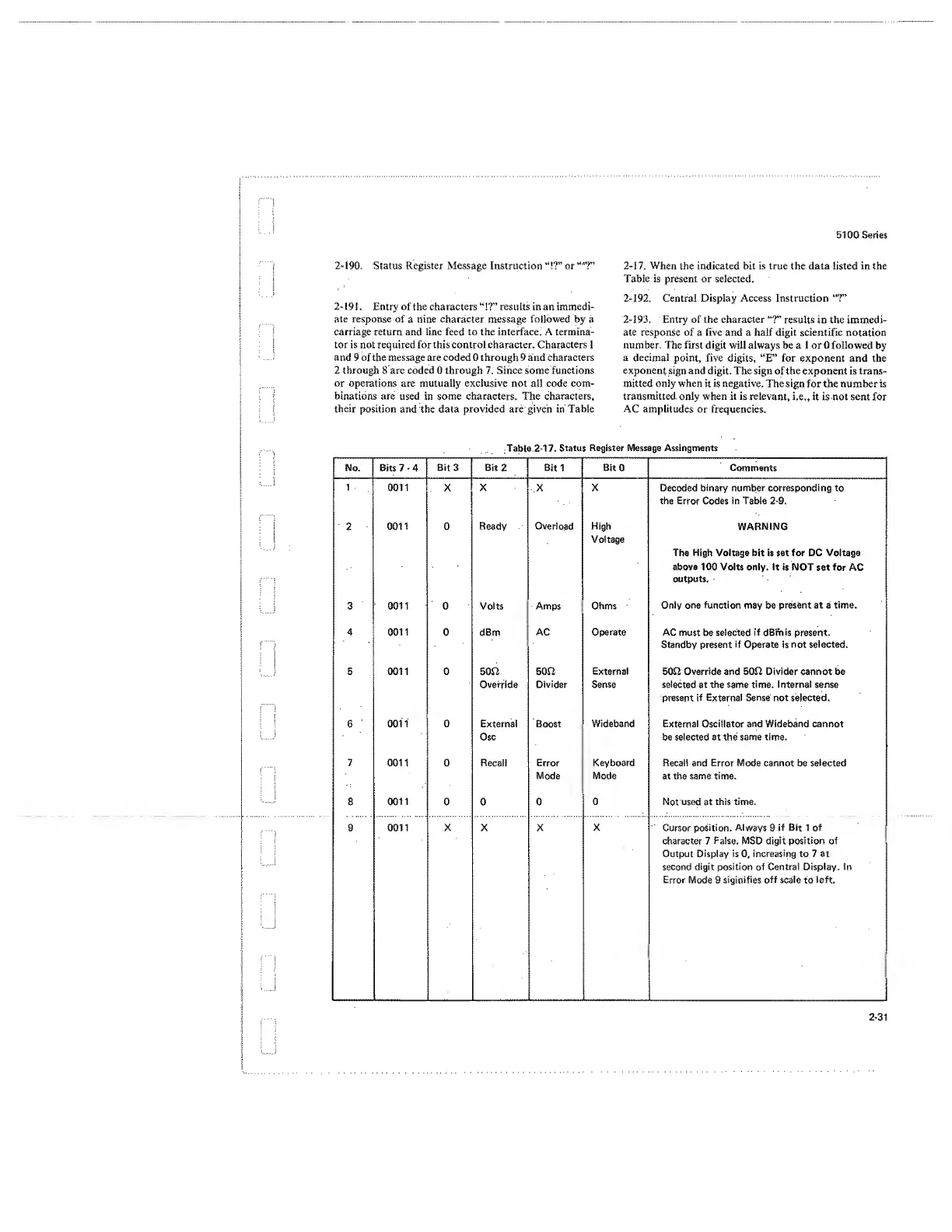
1 9 1 . Entry of the characters
“!?”
results in an immedi-
ate response
of a nine
character
message
followed
by a
carriage return and line feed to the interface. A termina-
tor is not required for this control character. Characters 1
and 9 of the message are coded 0 through 9 and Characters
2 through 8 are coded 0 through 7. Since some functions
or operations are mutually exclusive not all code com-
binations are used in some characters. The characters,
their
position and the data provided are given in Table
5100 Series
2-17.
When the indicated bit is true the data listed in the
Table is present or selected.
2-192.
Central Display Access Instruction
“7”
2-193.
Entry of the character
“?”
results
in the immedi-
ate response of a five and a half digit scientific
notation
number. The first digit will always be a 1 or
0
followed
by
a
decimal
point, five digits, “E” for exponent and the
exponent sign
and digit. The sign of the exponent is trans-
mitted only when
it is
negative.
The sign for the number is
transmitted only when it is relevant,
i.e„
it is not sent for
AC amplitudes or frequencies.
Table
2-17. Status
Register Message Assingments
Mo.
Bits 7
-
4
Bit 3 Bit
2
Sit
1
Bit
0
Comments
1
0011 X X X X Decoded binary number corresponding
to
the
Error
Codes in Table
2-9.
2
0011 0 Ready
Overload High
Voltage
WARNING
The High Voltage bit is set for DC Voltage
above 100 Volts only. It
is NOT
set
for
AC
outputs.
3 0011 0 Volts Amps
Ohms
Only one
function
may be
present
at a
time.
4
0011 0 dBm AC
Operate
AC must be selected
if
dBm is
present.
Standby present
if
Operate is
not
selected.
5 0011 0 50f2
Override
500
Divider
External
Sense
500 Override and 500 Divider cannot be
selected
at
the same time. Internal sense
present
if External Sense
not selected.
6
001
1
0 Externa!
Osc
Boost Wideband
External
Oscillator and Wideband cannot
be selected at the same time.
7 0011 0 Recall Error
Mode
Keyboard
Mode
Recall and Error Mode cannot be selected
at the same time.
8
0011
0 0 0
0
Not used at
this time.
9 0011 X X X
X
Cursor
position. Always
9
if Bit
1 of
character 7
False.
MSD digit
position
of
Output Display is
0,
increasing
to 7 at
second
digit position
of
Central Display. In
Error
Mode 9
signifies
off
scale
to
left.
 Loading...


