5100
Series
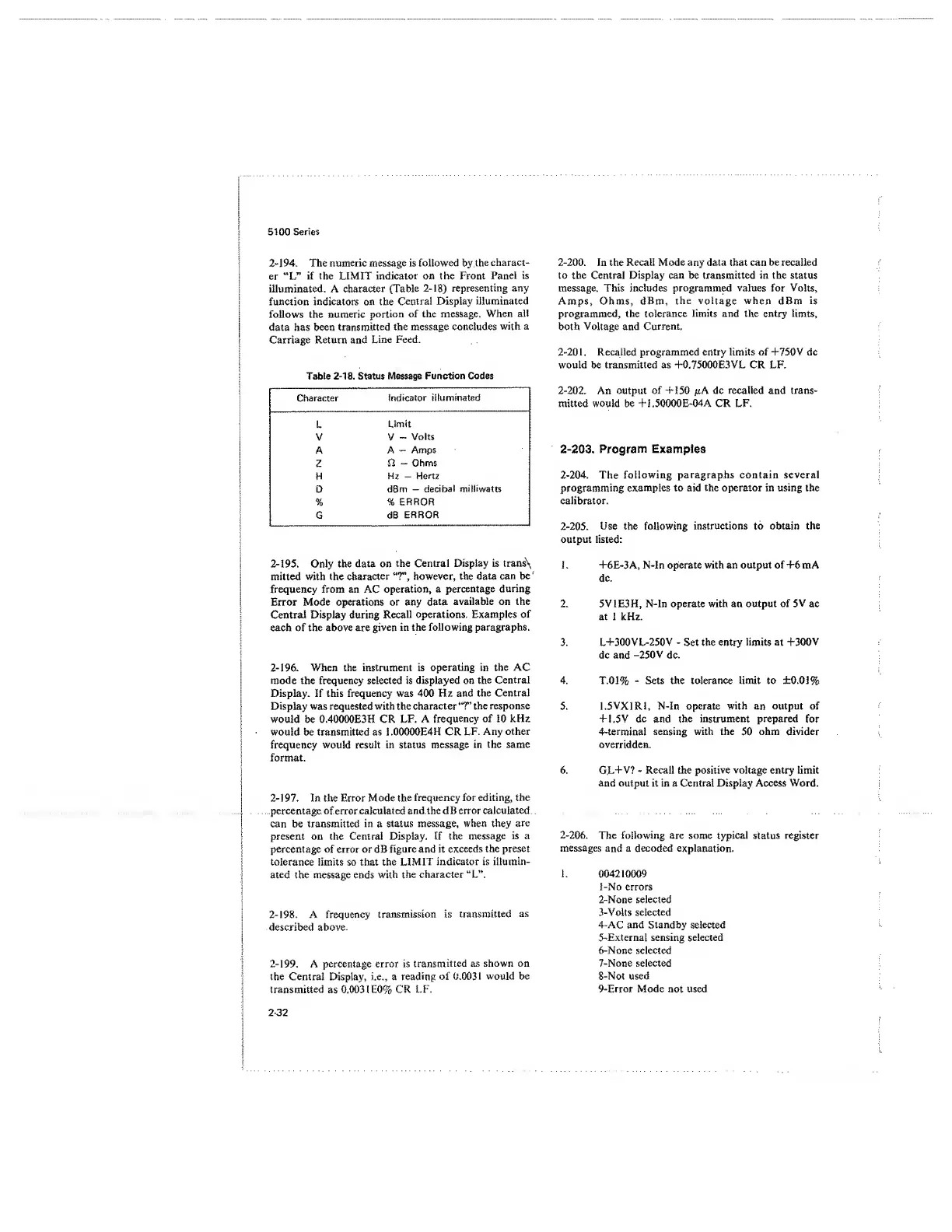
2-194.
The numeric message is followed by
the
charact-
er “L”
if the LIMIT indicator on the Front
Panel
is
illuminated. A character
(Table
2-18)
representing any
function indicators on the
Central Display illuminated
follows the numeric
portion of the message.
When
all
data has been
transmitted
the message concludes
with a
Carriage Return and
Line Feed.
Table
2-18.
Status Message
Function
Codes
Character
indicator
illuminated
L
Limit
V V
-
Volts
A A
-
Amps
Z
Q,
—
Ohms
H
Hz
-
Hertz
D
dBm
-
decibal milliwatts
% %
ERROR
G dB
ERROR
2-195.
Only the data on
the Central Display is trans\
mitted with
the
character
“T\
however, the data
can be
'
frequency from
an
AC
operation, a
percentage during
Error
Mode operations or any data
available
on the
Central
Display
during Recall
operations. Examples of
each of
the
above are given
in the following
paragraphs.
2-196. When the instrument is operating in
the AC
mode the frequency selected is displayed on
the
Central
Display. If this frequency was 400 Hz and
the Central
Display was requested with the character *T
the response
would be 0.40000E3H CR LF. A
frequency
of
10
kHz
would be transmitted as 1 .OOOOOE4H CR
LF.
Any other
frequency would result in status message
in the same
format.
2-197.
In the Error Mode
the
frequency for editing, the
percentage of error
calculated
and the dB error calculated
can be transmitted
in
a
status message, when they
are
present on the Central Display. If the
message
is a
percentage of error or dB figure and it
exceeds
the preset
tolerance limits so that the
LIMIT
indicator is illumin-
ated the message ends
with
the character "L”.
2-198.
A frequency
transmission is
transmitted
as
described above.
2-199.
A percentage error is
transmitted
as shown on
the Central Display, i.e., a
reading
of 0.0031 would be
transmitted as 0.003 1 E0%
CR LF.
2-200.
In the Recall Mode any data that can be recalled
to the Central Display can be transmitted in the status
message. This includes programmed
values
for
Volts,
Amps, Ohms, dBm,
the
voltage when
dBm
is
programmed, the
tolerance
limits and the
entry timts,
both
Voltage
and
Current.
2-201. Recalled programmed entry limits of +750V dc
would be transmitted as +0.75000E3VL CR LF.
2-202.
An output of -H50 /kA dc recalled and trans-
mitted would be +1.50000E-04A CR LF.
2-203.
Program
Examples
2-204.
The
following
paragraphs contain several
programming
examples to aid the operator in using the
calibrator.
2-205. Use
the
following
instructions
to
obtain the
output listed:
1.
+6E-3A, N-ln operate with an output of
4-6
m
A
dc.
2. 5V1E3H, N-In operate with an
output of
5V
ac
at 1 kHz.
3. L+300VL-250V
-
Set the
entry
limits
at
+300V
dc and
-250 V
dc.
4. T.01%
-
Sets the tolerance limit to ±0.01%
5.
1.5VX1R1,
N-In operate
with
an
output
of
41.5V
dc
and
the
instrument
prepared
for
4-terminal
sensing with the
50
ohm divider
overridden.
6. GL4-V?
-
Recall the positive voltage entry limit
and output it in a Central Display Access Word.
2-206.
The
following are
some
typical
status register
messages
and
a decoded
explanation.
I.
004210009
1-
No errors
2-
None selected
3-
Volts
selected
4-
AC
and Standby
selected
5-
External sensing selected
6-
None selected
7-
None selected
8-
Not used
9-
Error Mode not used
2-32
 Loading...


