Front Panel Operation
Basic Operation 4
4-13
Basic Operation
Whether your application involves measurement mode or transfer mode, you can
select certain measurement parameters. Among them is the Digital Filter Mode
and Restart threshold, accessible through the Setup Menu>Instrument Setup
menu. This and other measurement parameters are described in this section.
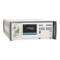
Interpreting the Display
The display shows the measured input voltage and frequency. Features and
functions of the display are summarized in Table 3-1 in Chapter 3. Refer to the
Specifications for resolution information for the different ranges.
The upper portion of the display shows the magnitude of the applied signal in
volts (V) or millivolts (mV). The lower portion of the display shows the frequency
of the applied signal in Hz, kHz, or MHz. When the input frequency is <9 Hz, the
frequency portion of the display is blank. When the Product has not taken a
measurement since power up, or an action such as an input or range change has
invalidated a measurement in progress, the display shows dashes instead of
numerals as in the figure below.
+/- 22.0 ppm (1 year) 83 days since calibration
2/06/15 10:52am
Set
Reference
Setup
Menu
Auto Range 2.2 V
Statistics
Input 2
Peak-to-Peak
Select
Current
Shunt
hvi008.eps
Text can also be shown for the measurement value to indicate the following:
• Over Range on the display indicates an overload.
• Under Range on the display indicates an under-range input.
Note
If dashes are shown for the current measurement, the true
resistance of the shunt is unknown. Refer to the A40 and A40A
current shunt in formation in Instructions for Current Measurements.

 Loading...