NTRODUCTION
AND SPECIFICATIONS
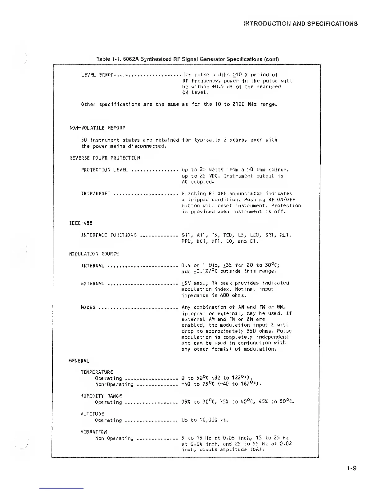
Table
1-1.
6062A Synthesized
RF Signal Generator Specifications (cent)
LEVEL ERROR....
.....for pulse widths >10
X
period
of
RF
Frequency, power
in
the pulse
will
be within
+0.5
dB of
the measured
CW Level.
Other specifications are the same as for
the
10 to 2100 Wz range.
NON-VOLATILE MEMORY
50 instrument states
are
retained
for
typicaUy
2
years, even with
the power
mains disconnected.
REVERSE POWER PROTECTION
PROTECTION LEVEL up to
25
watts
from
a
50
ohm source.
up to 25
VDC. Instrument
output is
AC coupled.
TRIP/RESET Flashing RF
OFF
annunciator indicates
a tripped condition. Pushing RF ON/OFF
button
will
reset
instrument. Protection
is provided when instrument is off.
IEEE-488
INTERFACE
FUNCTIONS SH1,
AH1,
T5, TEO,
L3, LEO, SR1, RLl
,
PPO, DC1, 0T1, CO, and El
,
MODULATION SOURCE
INTERNAL
0.4 or 1 kHz,
+3%
for
20 to 30°C;
add
+0.1%/°C outside this
range.
EXTERNAL
+5V
max.; IV peak provides
indicated
modulation index.
Nominal input
impedance is
600 ohms.
TODES
Any
combination of AM and FM
or
0M,
internal or
external, may be used-
If
external AM and
FM
or 0M
are
enabled, the modulation input
Z will
drop
to
approximately
560 ohms.
Pulse
modulation is
completely independent
and can be used in
conjunction with
any
other
form(s)
of modulation.
GENERAL
TEMPERATURE
Operating
0 to
50®C (32 to 122°F).
Non-Operating
-40
to
75°C
(-40
to 167°F).
HUMIDITY RANGE
Operating
95% to
30°C, 75% to 40°C,
45% to 50°C.
ALTITUDE
Operating
Up to 10,000 ft.
VIBRATION
Non-Operating .............. 5
to 15 Hz at 0.06 inch,
15 to 25 Hz
at 0.04 inch, and 25
to 55 Hz at
0.02
inch,
double amplitude (DA).
1-9
 Loading...