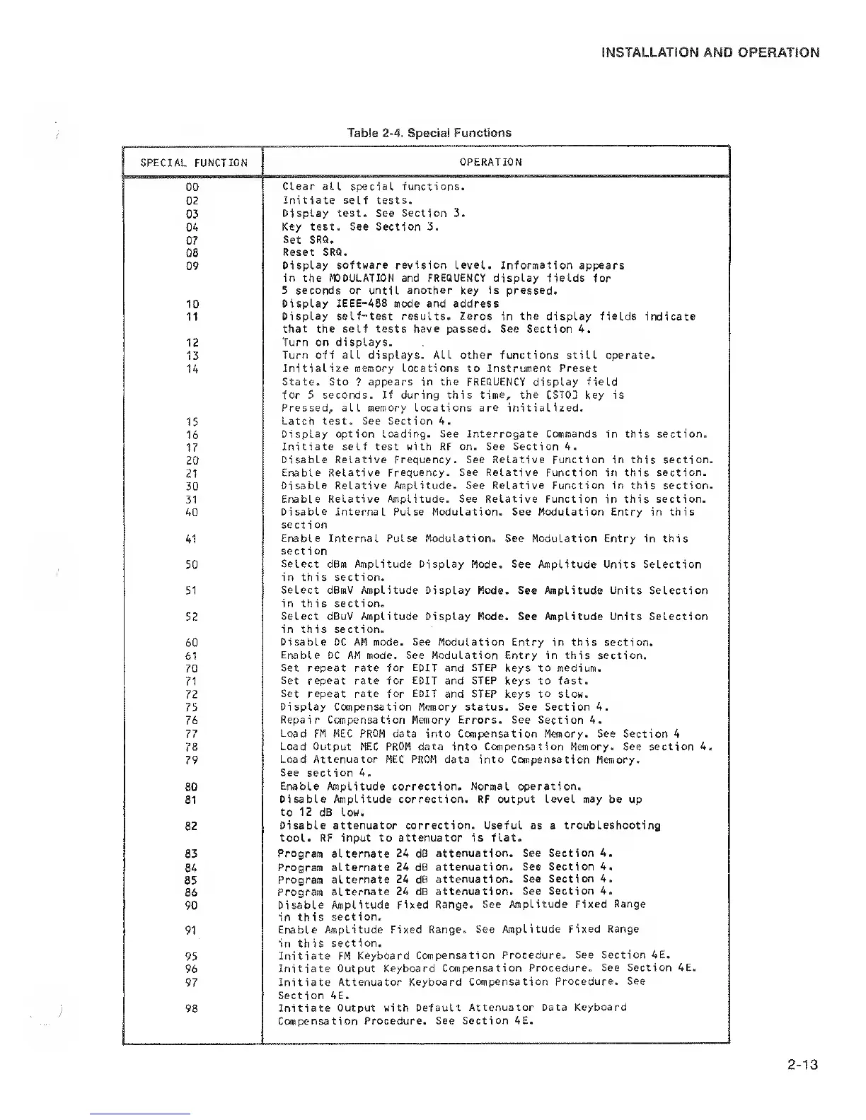
SPECIAL FUNCTION
OPERATION
GO
Clear all
special functions.
02
Initiate
self
tests.
03
Display
test.
See Section 3.
04
Key test. See Section 3.
07
Set SRQ.
08
Reset SRQ.
09
Display software revision level. Information
appears
in the MODULATION and FREQUENCY display fields for
5 seconds or until another key is pressed.
10
Display IEEE-488 mode and address
11
Display
self-test results. Zeros in the display fields indicate
that
the self tests
have
passed. See Section 4.
12
Turn on displays.
13
Turn off all displays. ALL other functions still operate.
14
Initialize memory Locations to instrument Preset
State. Sto
?
appears in the FREQUENCY display field
for 5 seconds. If during this time, the CST03 key is
Pressed, all memory Locations are initialized.
15
Latch test. See Section 4.
16
Display option loading. See Interrogate Commands
in this section.
17
Initiate self test with RF on. See Section 4.
20
Disable Relative Frequency. See Relative Function in this section.
21
Enable Relative Frequency. See Relative Function
in this
section.
30
Disable
Relative Amplitude. See Relative Function
in this section.
31
Erable Relative Amplitude. See Relative Function
in
this section.
40
Disable Internal Pulse Modulation. See Modulation Entry
in this
section
41
Enable Internal
Pulse Modulation. See
Modulation
Entry in this
section
50
Select dBm Amplitude Display Mode. See
Amplitude Units Selection
in this section.
51
Select dBmV Amplitude Display
Mode. See Amplitude Units Selection
in this section.
52
Select dBuV Amplitude
Display Mode. See Amplitude Units Selection
in this section.
60
Disable DC AM mode. See Modulation Entry
in
this section.
61
Enable DC AM mode. See Modulation Entry in this section.
70
Set repeat rate for
EDIT
and
STEP
keys to medium.
71
Set
repeat rate for
EDIT
and STEP keys to fast.
72
Set repeat rate for EDIT
and STEP keys
to
slow.
75
Display Compensation Memory status. See Section 4.
76
Repair Compensation
Memory Errors. See Section 4.
77
Load
FM MEC
PROM
data into Compensation Memory. See Section 4
78
Load Output MEC
PROM
data into Compensation Memory. See section 4.
79
Load Attenuator MEC
PROM
data
into Compensation Memory.
See
section 4.
80
Enable
Amplitude correction.
Normal operation.
81
Disable Amplitude correction. RF output Level
may
be up
to 12
dB low.
82
Disable attenuator correction. Useful as
a
troubleshooting
tool. RF input to attenuator is flat.
83
Program
alternate 24 dB
attenuation. See
Section 4.
84
Program
alternate 24 dB
attenuation. See Section 4.
85
Program alternate
24 dB attenuation.
See Section 4.
86
Program
alternate 24 dB
attenuation. See Section 4.
90
Disable
Amplitude Fixed Range.
See Amplitude
Fixed Range
in this
section-
91
Enable Amplitude Fixed
Range. See topLitude
Fixed Range
in this
section.
95
Initiate FM Keyboard
Compensation Procedure.
See Section 4E.
96
Initiate Output
Keyboard Compensation Procedure.
See Section 4E.
97
Initiate Attenuator
Keyboard Compensation
Procedure. See
Section 4E.
98
Initiate
Output with Default
Attenuator Data
Keyboard
Compensation Procedure,
See Section 4E.
 Loading...