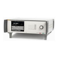
Pressure Controller/Calibrator
Rear-Panel Features
29
Rear-Panel Features
Rear-panel features (including all terminals, sockets, and connectors) are
shown in Table 8.
Table 8. Rear-Panel Features
1 3 4 52
8
9
1011
12
6
7
huo009.eps
Item Description
Switch Test Jacks
Switch test inputs used to connect a pressure switch to the Product for
pressure switch testing. See Switch Test.
Caution
To avoid damage to the Product, do not connect more
than 30 V (with respect to Chassis ground) to these
terminals.
System Bus
Connector
Connector for system stacking. See System Stacking for more information.
24 V External Drivers
The external drivers are 24 V dc outputs that can be individually controlled
in the Setup menu. Drivers also operate specific accessories such as the
Contamination Prevention System (CPS). See Contamination Prevention
System (CPS).
When an accessory is connected and turned on in the Setup menu, the
software automatically reserves the use of that driver for the accessory and
changes the state of the driver as necessary to operate the accessory. For
more information on the drivers, see External Driver Configuration.
Rear USB Port
USB 2.0 remote operation interface – When this port is used to connect the
Product to a PC, the Product is seen by the PC as a serial COM port or
external drive. Screen captures and test results can be moved from the
Product to the PC. Refer to the Remote Programmers Manual for more
information on remote operation.
Ethernet Connector
100 Base/T Ethernet Connector for Remote Operation Interface. Refer to
the Remote Programmers Manual for more information on remote
operation.

 Loading...