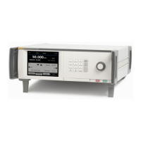
Pressure Controller/Calibrator
Configure the Driver
57
Configure the Driver
Turn the CPS and/or isolation valve accessories on from the Instrument Setup
menu (Setup>Instrument Setup). Both require the correct pneumatic
connections and electrical connections. Touch the External 24V tab to see or set
the state of the external drivers. Touch the Isolation Valve tab to set up the
isolation valve.
Drivers are identified in the External 24V menu and on the rear panel of the
Product as DRV1, DRV2, DRV3, DRV4 (see Figure 16). Each solenoid uses two
wires, one wire goes into each connector.
• DRV1 uses the two top left inputs
• DRV2 uses the two top right inputs
• DRV3 uses the two bottom left inputs
• DRV4 uses the two bottom right inputs
Driver 2
Driver 4
Driver 1
Driver 3
huo031.eps
Figure 16. Driver Location
Several of the drivers support specific accessories such as the CPS and Isolation
valve for system stacking.
• DRV1: CPS Valve
• DRV2: CPS Valve
• DRV3: CPS LED
• DRV4: External Isolation Valve
See the associated appendices for additional information on these accessories.
The External 24 V menu (Setup>Instrument Setup>External 24V) also shows
the driver states for any auxiliary chassis when working in a system with multiple
chassis.

 Loading...