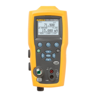
Pressure Calibrator
Calibration Adjustment
7
mA Loop Performance Check
Loop voltage does not have traceable specifications, this is a functional check
only.
1. Push to get LOWER in the display above .
2. Push to show CONFIG and then push again to show SELECT on the
display.
Type of measurement should be flashing in the lower display.
3. Push until mA flashes.
4. Push .
5. The type of measurement/source flashes. Push until MEAS/24V flashes.
6. Push to begin supplying loop power.
7. Connect the Product red banana jack (V mA) to the 8846A HI Input.
8. Connect the Product black banana jack (COM) to the 8846A LO Input.
9. Set the 8846A to dc volts range. The voltage measured should be between
22 V and 30 V.
10. When a Product fails any verification step, adjustment or repair is
recommended by Fluke.
Calibration Adjustment
The Product has an electronic calibration process. There are no mechanical
adjustments and the calibration is done with the case closed. A serial
communications port is used for the calibration process to send commands and
receive readings. The normal RS232 interface is used. Calibration can be done
with a terminal program or an automated-calibration program can be written with
programs like MetCal. In this manual, only the serial terminal mode is described.
Table 1 lists the required equipment.
Initiate Communication
Terminal communications can be set up with terminal communication software
on a PC such as HyperTerminal or Ucon. Connect the RS232 cable to the 5-pin
Lemo on the side of the Product. The other end of the cable connects to the
terminal/PC serial port.
Terminal Settings:
• Bits per second: 9600
• Data bits: 8
• Parity: None
• Stop bits: 1
• Flow control: none
• Local echo: on

 Loading...