Maintenance
Calibration 3
3-13
Table 3-9. DC and AC mA Test
Input
Step Range A Freq. Display Reading
1 40 mA dc +35 mA 34.80 to 35.20 DC
NOTE
To enter AC mA, press and hold button for 2 seconds
2 40 mA ac 35 mA 1 kHz 34.45 to 35.55A AC
4. Set the output of the Current Calibrator to standby and connect it to the 10A and
Common input terminals of the UUT.
5. Return the UUT to A DC.
6. Set the Current Calibrator to the output shown in Table 3-10, and verify that the UUT
display reading is within the limits shown.
Table 3-10. DC Amps Test
Step
Input
Display Reading
Range A
2 10A dc +10A 9.93 to 10.07 DC
Calibration 3-22.
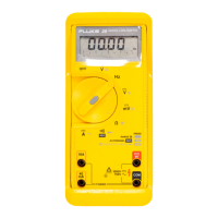
Calibrate the meter once a year to ensure that it performs according to specifications.
Calibration adjustment points are identified in Figure 3-5.
Use the following procedure to calibrate the Fluke 76:
1. Set the DC Voltage Calibrator to 0 volts.
2. Select the function on the meter.
3. Connect the DC Voltage Calibrator to the VΩ and COM input terminals of the
UUT.
4. Set the DC Voltage Calibrator for an output of +3.5V dc.
5. The UUT should display 3.500V dc ± 0.001. If necessary, remove the four case
screws and top cover, and adjust R21 to obtain the proper display.
6. Set the UUT to the function, and set the source for an output of 3.500V ac at
100 Hz.
7. The UUT should display 3.500V ac ± 0.002. If necessary, remove the four case
screws and top cover and adjust R34 to obtain the proper display.

 Loading...