Certifying Twisted Pair Cabling
Twisted Pair Autotest Results
3-17
3
Resistance
Resistance results show the dc loop resistance for each cable
pair. The smart remote shorts the end of each pair to create
the loops. A pair’s resistance depends on the integrity of
the contacts in the connector, the length of the pair, and its
wire gauge.
Resistance problems always affect other tests. For example:
•
A link that is too long has higher-than-normal
resistance and will fail the length test.
•
High-resistance connections reflect signals that cause
the return loss test to fail. The tester’s HDTDR test tells
you the distance to the bad connection.
Most standards do not have a limit for resistance. The tester
shows an
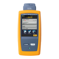
i when no limit is available. Figure 3-11 shows the
resistance results screen.
Tip: The resistance test in Single Test mode features a
scanning function that runs the resistance test
continuously. This function is helpful for locating
intermittent resistance faults.
amd85f.eps
Figure 3-11. Resistance Results
Characteristic Impedance
Notes
Most test limits do not require the characteristic
impedance measurement. Characteristic impedance
is not displayed for these limits.
Impedance measurements require a cable at least
13 ft (4 m) long. The tester shows Unknown for
cables shorter than this.

 Loading...

