Fluke 19xB-19xC-2x5C
Service Manual
5-14
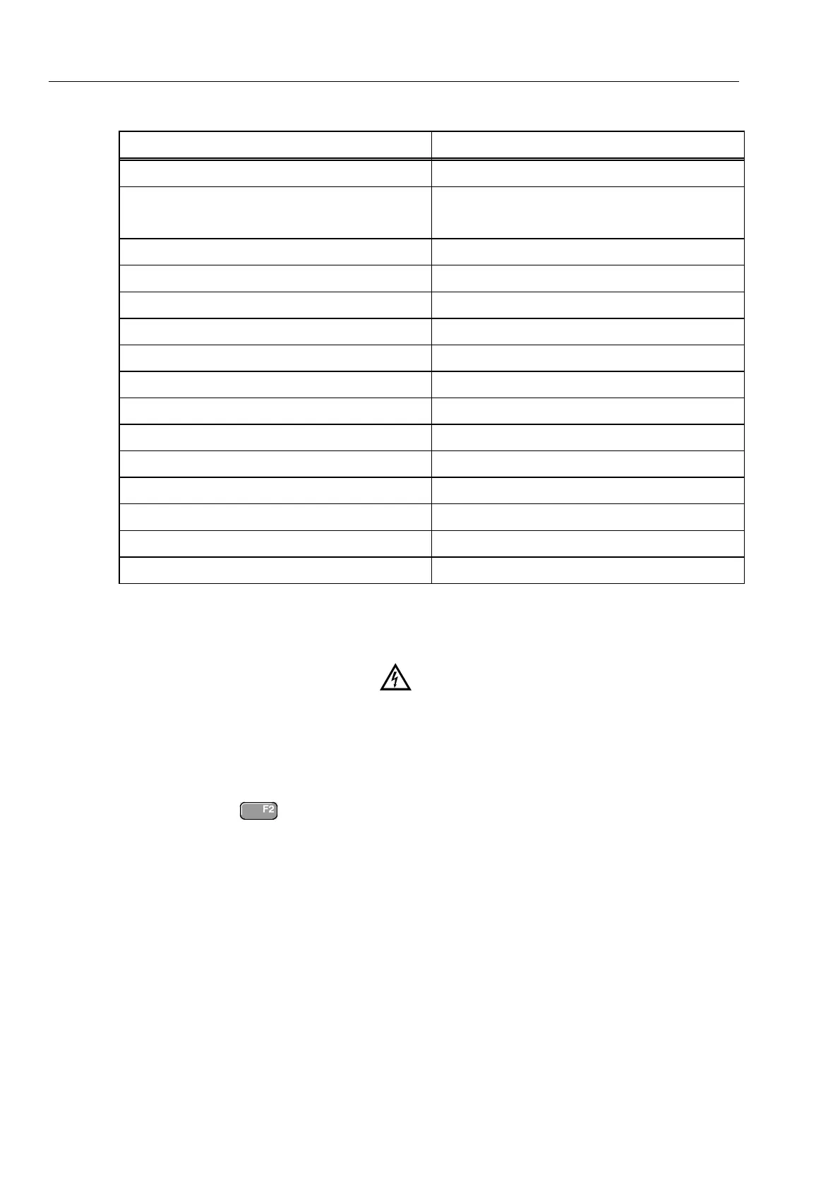
Table 5-4. Input A&B Gain Calibration Points
Cal step UUT input value (5500A NORMAL)
CL 0824 250 mV
CL 0799
Not for software versions V05.01 and V05.02
5 mV
CL 0800 12.5 mV
CL 0801 25 mV
CL 0802 50 mV
CL 0803 125 mV
CL 0805 500 mV
CL 0806 1.25 V
CL 0807 2.5 V
CL 0808 5 V
CL 0809 12.5 V
CL 0810 25 V
CL 0811 50 V (set 5500A to OPR!)
CL 0812 125 V
CL 0813 250 V
5.6.6 DMM Volt Gain
Warning
Dangerous voltages will be present on the calibration source
and connection cables during the following steps. Ensure that
the calibrator is in standby mode before making any connection
between the calibrator and the test tool.
Proceed as follows to do the DMM Volt Gain calibration.
1. Press
to select the first calibration step in Table 5-5.
2. Connect the test tool to the 5500A as shown in Figure 5-7.
 Loading...