M
Michael Martin Jr.Aug 3, 2025
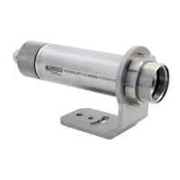
Why does the temperature fluctuate on my Fluke Thermalert 4.0?
- JJessica AtkinsonAug 3, 2025
If the temperature readings on your Fluke Accessories fluctuate, it might be due to incorrect signal processing settings. Try correcting the Peak/Valley Hold or Average settings. Also, ensure the instrument has a proper ground connection by checking the wiring and grounding.