Memo generation base band chip
That made the system structure to separate
The periphery equipm nd all of them use the 52M
System clock simu
LPA0 is select
set signal.
Display data is transferred to video RAM in LCD driver by I/O port in DMA mode. So system
Can response quickly and multimedia runs fluently without mosaic or picture feeling. Three
Common-anode LEDs in charge of background light supplying. Three voltage sensitive resisters are
Needed to protect the LCD from electrostatic harm and extend the life of LCD.
ry and all the periphery equipments used the same bus based on the 1
st
very slow. Considering that, MTK have altered the hardware
ents (like LCD and NAND etc.) from memory bus a
ltaneously
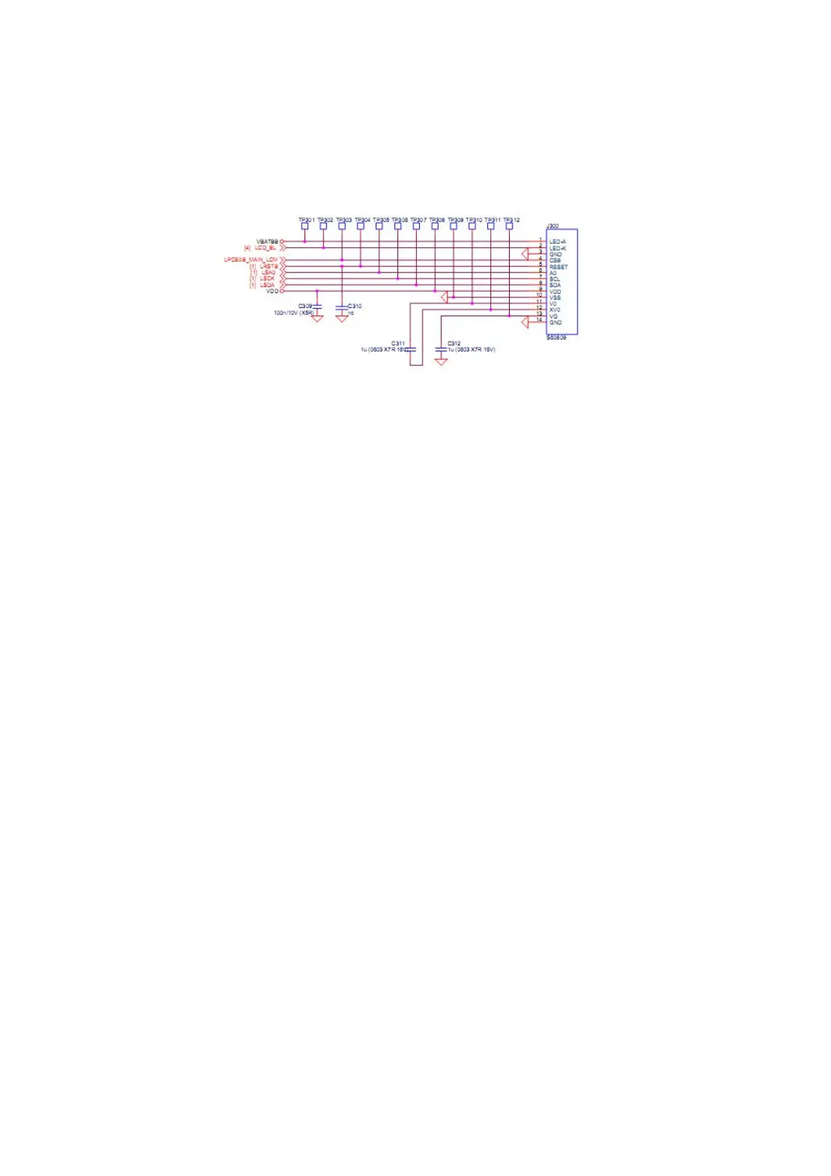
Figure 3.2.9 LCD interface circuit
LCD use series type LCD and four control bus (LPCEOB_MAIN_LCM is chip select signal;
bus for register and commend; LWRB is LCD writes strobe; LRDB is LCD read strobe, LRSTB is re
LCD is controlled by baseband IC.