6
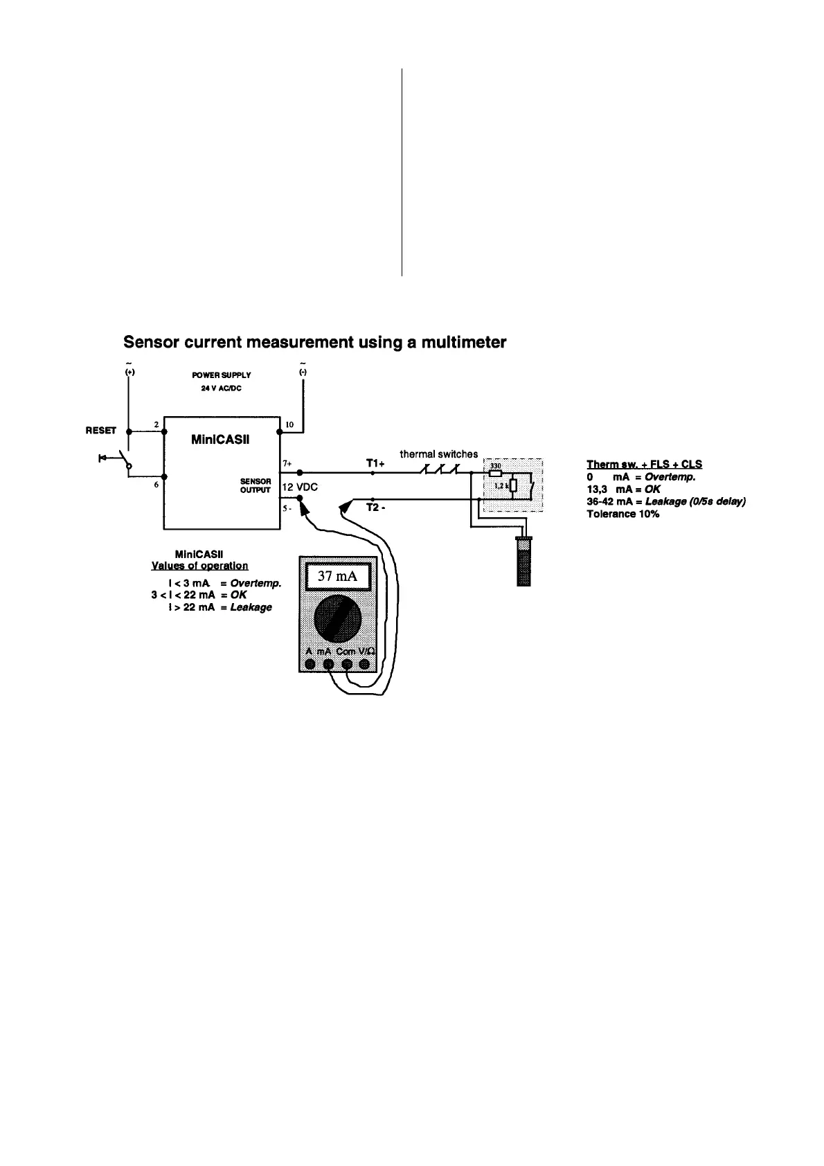
Connect a multimeter in series with the sensors or
use the ITT Flygt sensortester “ST-1” (FD part no.
10-581700) to measure the current in the sensor
circuit. See figures below.
“ST-1” is not yet prepared to handle the new sensor
FLS10.
The figures on page 2 is used as reference to deter-
mine the status of the sensors (sensor connections).
Circuits with CLS require some extra consideration.
Connected with wrong polarity the CLS draws a zero
current. The CLS can then be considered not connec-
ted.
Wrong polarity results in 0 mA for circuit (3). Circuit (4)
is reduced to the same as circuit (1).
As opposed to the FLS and FLS10, the CLS has a
built-in alarm delay of 5 seconds.
Since the MiniCASII has only one leakage indication
lamp, an alarm from the CLS or the FLS looks the
same.
For circuit (4), this means that a leakage alarm can
not be attributed to either of the two sensors just by
looking at the MiniCASII. To make out the tripping
sensor without lifting the pump, a measurement of the
sensor current is necessary.
General procedure to check the status of the sensors
1. Close the sensor circuit by connecting the multi-
meter test leads according to figure above or on
next page.
2. From the moment contact is made, observe the
sensor current for at least 5 seconds (to await a
possible CLS alarm current).
3. Switch polarity of the sensor leads (5, 7) and repeat
steps 1 and 2.
4. Identify the actual sensor circuit with the help of the
first page figure and analyse the sensors’ status.
5. In case circuit (4) is used: By using the wrong po-
larity and delay properties of the CLS, it is possible
to conclude if a leakage alarm is attributed to the
CLS or FLS.
6. To ensure that the polarity is right after the mea-
surement, restore the connection resulting in the
largest current.
Checking the sensor circuit and fault finding
 Loading...