EasyManua.ls Logo

Fnirsi 2C23T User Manual

Fnirsi 2C23T
184 pages
To Next Page IconTo Next Page
Page #1 background imageLoading...
Page #1 background image
2C23T
Dual channel oscilloscope
multimeter manual
Question and Answer IconNeed help?

Do you have a question about the Fnirsi 2C23T and is the answer not in the manual?

Fnirsi 2C23T Specifications

General IconGeneral
Screen size2.8 inches
Display resolution320x240
DisplayColor LCD
Frequency Range0Hz~10MHz
Battery TypeLithium battery

Summary

Notice to Users

1. Product Introduction

2. Panel Introduction

Oscilloscope Channel 1 Input

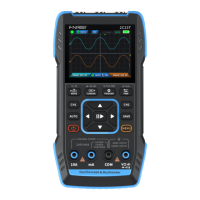
Identifies the input port for the first oscilloscope channel.

Oscilloscope Channel 2 Input

Identifies the input port for the second oscilloscope channel.

Signal Generator Output Port

Identifies the output port for the signal generator.

Screen Display Area

Points to the device's main screen.

Control Button Layout

Highlights the main control button layout.

Multimeter Measurement Ports

Indicates the ports for multimeter measurements.

3. Device Parameter

4. Buttons & Functions Introduction

Oscilloscope Key Operation Guide

Explains button functions for oscilloscope mode.

1.2 Oscilloscope - Interface Description

Operation Pause and Time Base Adjustment

Explains waveform pause and time base adjustment.

Channel Status and Signal Generator Indicators

Shows channel status and signal generator output indicators.

Trigger Level and Configuration Settings

Oscilloscope Channel 1 & 2 Configuration

Channel 1 Waveform Movement Control

Channel 2 Waveform Movement & Cursor Control

Parameter Measurement Display Management

1.3 Oscilloscope - Waveform Screenshot Saving

Saving and Viewing Waveform Screenshots

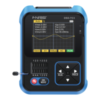
Instructions for saving and viewing waveform screenshots.

1.4 Oscilloscope – Parameters

2.1 Function Signal Generator - Key Description

2.2 Function Signal Generator - Interface Description

Signal Generator Output & Battery Status

Explains output status and battery indicators for the signal generator.

Waveform Selection and Adjustment Parameters

Lists waveform types and describes parameter adjustment.

2.3 Function Signal Generator – Parameters

3.1 Digital Multimeter - Key Description

3.2 Digital Multimeter - Interface Description

Multimeter Display Elements Overview

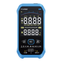
Explains range scale, HOLD, REL, display area, and gear indicators.

Power Indicator Status

Explains the power indicator.

3.3 Digital Multimeter Probe Interface Introduction

Multimeter Probe Connection Guidelines

Details probe connections for high current, low current, and general measurements.

Multimeter Gear Operation Details

3.4 Parameters

5. Setting

Setting Categories and Specific Details

Lists setting categories and provides specific details for each.

6. Upgrade

7. Customize Startup Logo

8. Common In-circuit Testing Methods

Battery & DC Voltage Measurement Guide

Guide for measuring battery and DC voltages.

Crystal Oscillator & PWM Signal Measurement

Signal Generator & Household Electricity Measurement

Power Ripple & Inverter Output Measurement

Amplifier/Audio & Automotive Signal Measurement

Infrared Remote Control & Sensor Signal Measurement

9. Notice

10. Production Information

Related product manuals