24 – FNM® Series HPE – Installation Manual
Figure 24 - Connection diagram of the double water intake (stern drive
installations)
In the case of twin installations (two engines), each engine
must have its own sea water circuit separate and independent
of the other engine.
5.4 Exhaust system
The installation of the exhaust system depends on the position
of the engine with respect to the waterline of the boat.
Failure to follow the rules contained in this paragraph may lead
to the infiltration of water into the engine, resulting in damage.
Comply with the instructions.
Correct positioning of the engine inside of the boat is
the responsibility of the installer who must respect
the waterline position.
5.4.1 Engine in stern drive configuration
In case of stern drive installations the correct positioning of the
engine depends on the specifications of the stern drive
installed.
Refer to paragraph 4.2 –
Engines with Mercruiser Bravo® stern drive on page 14 to see
the correct positioning of the stern drive assembly and the
engine inside the engine compartment.
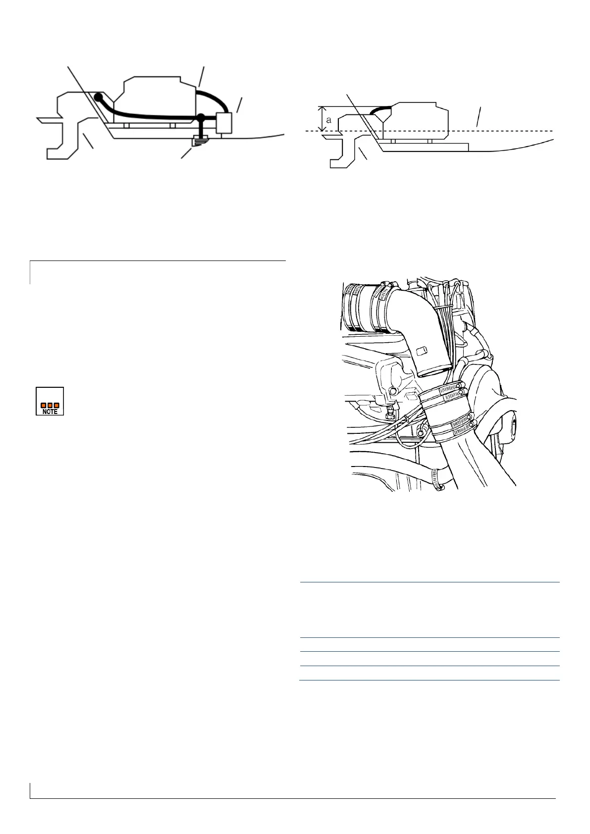
Figure 25 - Engine exhaust in stern drive configuration
In case of stern drive installations the upper exhaust elbow (on
the engine) must be fixed with a sleeve of appropriate
diameter to the discharge lower elbow (on the stern drive), as
shown in Figure 26. Use two clamps to each end of the sleeve
to ensure the appropriate seal.
Figure 26 - Exhaust sleeve in Stern drive version
The minimum height a in Figure 25 between the waterline and
the highest point of the upper exhaust elbow (on the engine) is
shown in the following table:
Distance a between
the waterline and the
highest point of the
exhaust [mm]
5.4.2 Engine in Inverter / JetDrive / Saildrive
configuration
In case of inverter, JetDrive or Saildrive installations the upper
discharge elbow must be connected to the exhaust outlet on
 Loading...