FNM® Series HPE – Installation Manual – 31
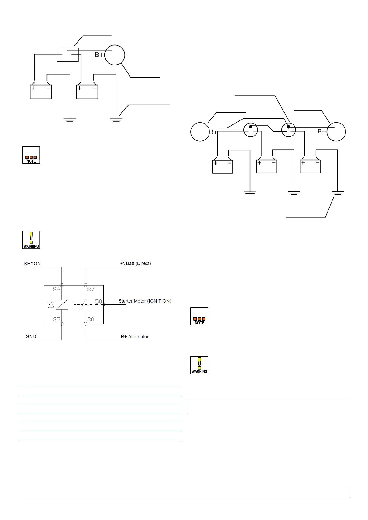
Figure 34 - Wiring diagram for single-engine, double battery
installation.
Some load dispatchers do not allow the energizing of
the alternator to charge the battery.
In the presence of load dispatcher, depending on the
model and type of dispatcher, it can happen that the
alternator is not energized and the battery is not
recharged. In this case it is necessary to use a timed relay
connected as in Figure 35 sotto to temporarily energize
the alternator and allow the batteries charging.
Use only relays that match the codes: Writtin
Electronic® 600 100; Wehrle® 51 233 016; Imel:
I18086.
Figure 35- Wiring diagram of timed relay connection for load
dispatcher
Connect the pins using the minimum cross sections
shown in the table:
3. Twin installation, two batteries: connect the batteries to
the two engines as in case 1, keeping the two circuits
separate.
4. Twin installation, three batteries: recommended
connection in case of twin installations and the need for
redundancy for selective charging of multiple batteries.
Follow the wiring diagram below. Two battery exchangers
provide the possibility of using and charging the various
batteries individually or in parallel connection by means of
manual selection.
Figure 36 - Wiring diagram of three batteries in twin installation.
6.2.3 Ground circuit
Make sure that the frames of all metallic elements (including
transom, inverters, etc ...) in the engine compartment are
electrically connected to each other and to ground with cable
of suitable diameter (see table in paragraph 6.2.1 – Cables
diameter and length – on page 29).
The galvanic currents generated between different
metals can, in some instances, lead to premature
corrosion of the metal elements in contact with the
sea water.
For engine installations on metal hulls, it is
necessary to study an appropriate electrical
insulation system between the engine and
transmission, and use a insulated pole engine
control system (see chapter 8.4 – Insulated Pole Kit
on page 45).
6.3 Control Unit
The engine control unit (hereafter ECU - Electronic Control
Unit) is a complex electronic assembly that manages the
operation of the engine in all its aspects.
The ECU is enclosed in a metal box with IP67 protection
against external agents.
Ground point on
the crankcase
Ground point on the crankcase
 Loading...