34 – FNM® Series HPE – Installation Manual
Figure 39- Instruments installation on the dashboard
Additional instruments are installed on the dashboard as in the
image Figure 39. Refer to the table above for the hole size
required for the installation of each instrument.
6.5.2 Panel wiring connectors
The CANBUS panel wiring is equipped with the following
connectors:
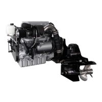
Figure 40 - Master Tachometer Connector (Tachometer - 9 pins
connected)
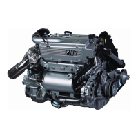
Figure 41 - Speedometer Connector (Speedometer - 6 pins
connected)
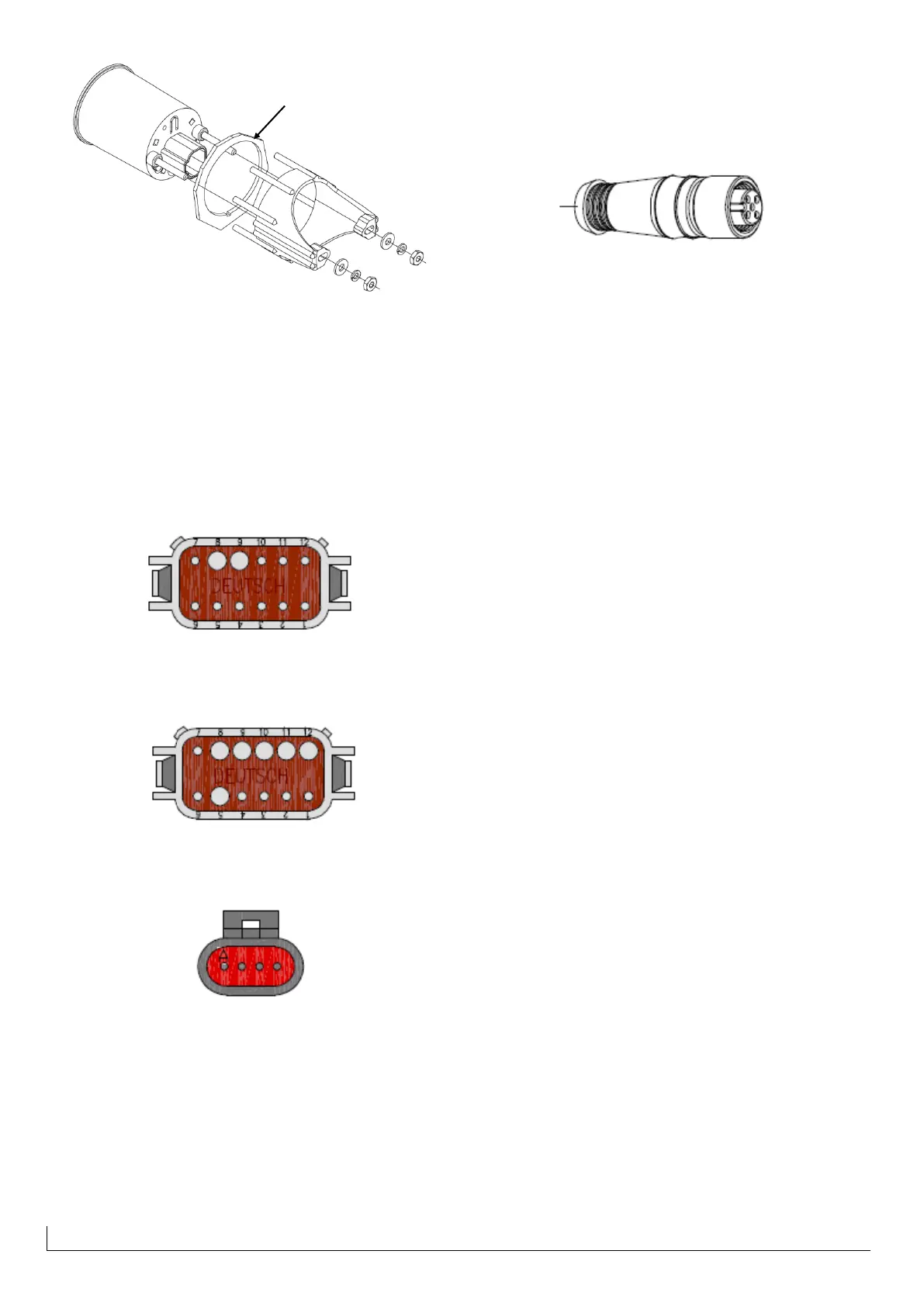
Figure 42 - First Slave Tool Connector (5 pins)
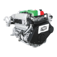
There is also a round connector (5 pin) that provides a direct
connection to the engine control unit for monitoring the
sensors detected through the standard J-1939:
Figure 43 - MOLEX connector for NMEA2000 (5pin)
It is possible to use an optional adapter to convert this signal in
the standard NMEA2000 to interface the engine with devices
using this standard. See paragraph 8.5 – Maretron®
NMEA2000 Control Unit on page 45.
 Loading...