FNM® Series HPE – Installation Manual – 35
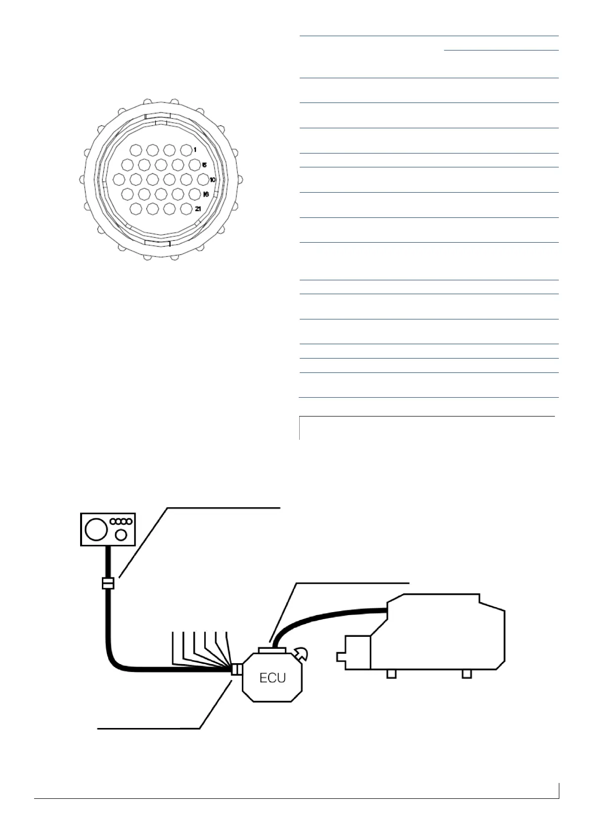
All the wires of the panel start from the extension connector,
that carries the electrical signals to and from the engine
compartment:
Figure 44 - TE® extension connector (24-pin) - Front View
The Pin map of the panel connector and extension cable is as
follows:
Stern drive oil
level alarm
Male "STERN
DRIVE"
Fastom
6.6 Basic electrical connections
The engine is connected to the control unit, to the extension
cable and to the instrument panel must be made as follows:
Figure 45- Basic electric connections wiring diagram for installations with single panel
Amphenol® Connector 64-PIN
Transmission oil level alarm
Air/Paddlewheel
temperature
 Loading...