FNM® Series HPE – Installation Manual – 43
8 Accessories
8.1 Heating Kit (Boiler)
The kit boiler allows the extraction of a part of the cooling
liquid to feed, with the heat produced by the engine, an
external thermal device.
The kit varies depending on the engine model. Even the
sampling points and the re-entry of the cooling liquid extracted
depend on the model of the engine.
HPE 40S/80/80SD/ 110/110JD
HPE 40/150/150JD/170/
170JD/190/190JD
The diameter of the heating pipes is 16 mm (5/8 in). All
elements of the heating circuit must withstand temperatures up
to 130°C and pressures up to 3 bar.
Follow the diagrams shown. Do not change the
fittings size or location as this will damage the
engine.
Make sure that the heating fitting is with closed
circuit and there is no leakage of coolant. Check the
correct operation of the system.
In the heating kit installation it is always required to add two
valves in correspondence of the sampling points (flow) and
return (re-entry) in the circuit for isolating, where necessary,
the heater and facilitate maintenance operations.
When connecting the heating kit it is necessary to restore the
coolant level in the tank to compensate the volume of liquid
which is absorbed by the heater circuit.
It is also necessary to bleed the circuit to ensure the absence
of air.
After installation, check the correct operation of the kit and that
the engine performance is maintained. Check the coolant level
in the tank and check for leaks.
The engine operation with low coolant level
quickly leads to overheating, causing damage to
the seals and internal parts of the engine.
Follow the instructions in the following paragraphs for the
correct installation of the heating kit.
8.1.1 Engine family 1.3 HPE
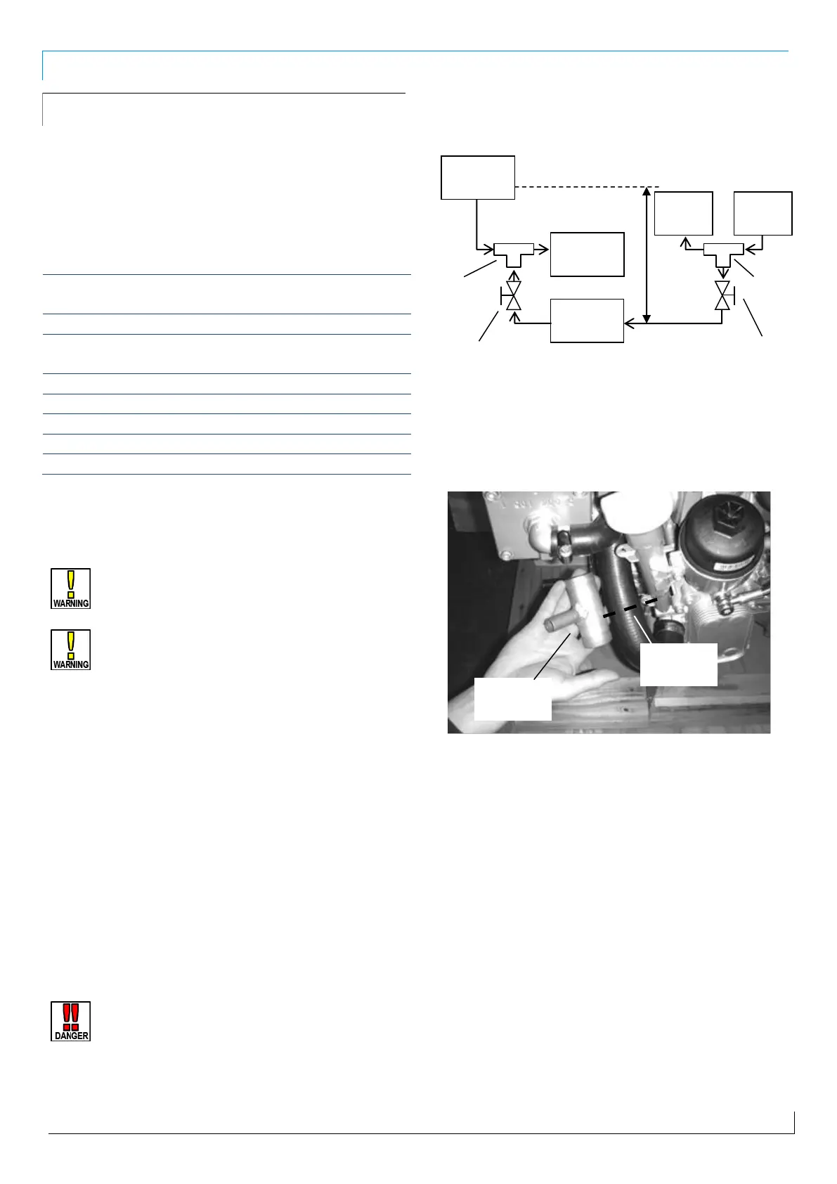
To connect the kit follow the diagram below:
Figure 53 - Wiring diagram for heating kit on 1.3 HPE base engine
Insert the three-way delivery fitting cutting the sleeve between
the thermostat and oil cooler in the point shown in the
following image:
Figure 54- Sleeve to be cut to connect the boiler kit delivery
connection on 1.3 HPE base engines.
Connect the two halves of the cut sleeve at the ends of the 32
mm (1 ¼ in) diameter fitting , and then connect the input of the
heater circuit at the 16 mm (5/8 in) diameter end.
Insert the three-way return fitting cutting in half the sleeve
between the expansion tank and the coolant pump as in the
following figure:
Return valve
(not provided)
Delivery valve
(not provided)
 Loading...