FNM® Series HPE – Installation Manual – 45
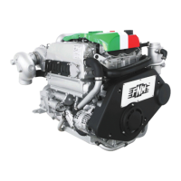
Figure 59 - Wiring diagram for heating kit on 3.0 HPE base engine
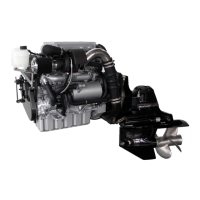
Screw the flow connection on the head, near the cooling water
temperature sensor, removing the nut M16x1.25 in the point
shown in the following image:
Figure 60 - Installation point of the boiler kit delivery connection on
3.0 HPE base engines.
Connect the 16 mm (5/8 in) diameter fitting to the heater input
circuit .
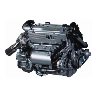
Insert the three-way return fitting cutting the sleeve between
the head and the connection pipe between the expansion tank
and auxiliary thermostat as shown in the following image:
Figure 61 - Installation point of the boiler kit return connection on 3.0
HPE base engines.
Connect the two halves of the sleeve cut at the ends of the
connector while preserving the orientation shown in Figure 61
Connect the free end of the16 mm (8.5 in) diameter fitting to
the heating circuit output .
Use cable clamps provided with the kit to attach the sleeves to
the fittings.
8.2 Accessories Additional Pulley (PTO)
The engines of the HPE range may be prearranged with an
additional power take-off on the engine shaft. This possibility
involves the installation of an additional pulley for trapezoidal
toothed belts with one or more grooves.
Additional Pulley order code
already supplied with engine
3.017.016.1
with adapter 3.105.222.1
The pulley coupling with the accessory device must be
correctly sized. The technical features of the additional pulley
vary depending on the model of the engine and are expressed
in the following table:
Number and Type of Additional
Grooves
1 x V-Belt Sect. Z/SPZ ISO
4183:95
During the installation it is necessary to check:
1. The maximum power which can be transmitted through
the pulley
Maximum radial
force given by
tensioning
Maximum
misalignment
allowed
*: mm of misalignment between the pulleys on the distance
between the shafts:
Return valve
(not provided)
Delivery valve
(not
supplied)
 Loading...