Do you have a question about the Forbes Marshall CODEL EnergyTech 300 Series and is the answer not in the manual?
Explains the requirement for monitoring dust collectors and emissions to atmosphere.
Details the operating principle, units, temperature and measurement ranges for the device.
Lists the available analogue, digital, and alarm outputs, and connection types.
Details material, weatherproofing, power requirements, display, and status LEDs of the unit.
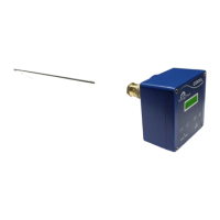
Describes the material, available lengths, and protection of the intrusive probe.
Specifies the material and core colours for mains and output cables.
Provides factors to consider when choosing the optimal position for the sensor probe.
Details the process for manufacturing and attaching a mounting stub to steel stacks.
Describes how to create and attach a mounting plate and stub for thin-walled stacks.
Explains how to attach the sensor head to the probe and mount it onto the stub.
Provides instructions on how to connect the mains cable to the device connector.
Details wiring procedures for volt-free and 24V output connectors.
Explains how to select between 24V and volt-free signal outputs.
Shows wiring diagrams for connecting mains and power to the ET301 and ET302.
Describes the steps for powering on the device and waiting for the system to initialise.
Details the menu path and procedure for performing a zero calibration.
Explains how to set the span calibration target and initiate an insitu span calibration.
Explains the importance of CF_m and CF_c and how to set them via the menu.
Details how to set the CF_c offset factor using the device menu.
Explains how to configure the measurand unit, zero, and span for mA outputs.
Details how to configure relay output measurand unit, direction, and trigger level.
Explains how to configure the signal damping time for the device.
Guides on establishing a cleaning routine for the probe based on build-up.
Explains the bridging condition and how to adjust cleaning intervals.
Provides steps for diagnosing and handling serious instrument failures, including returning for repair.
Explains the use of function 03 for obtaining register contents and the request/response frame formats.
Details the format of the slave response frame and communication parameters.
Lists available MODBUS registers for reading device data, including values and status.
Provides general memory map details for RAM, EEPROM, units, modes, baud rates, and protocols.
Details MODBUS addresses, local names, Codel addresses, and data types for COMMS RAM registers.
Details MODBUS addresses, local names, Codel addresses, and data types for COMMS EEPROM registers.
Lists available commands for the device.
| Brand | Forbes Marshall |
|---|---|
| Model | CODEL EnergyTech 300 Series |
| Category | Monitor |
| Language | English |